Modeling
If you use GBTEC Work Orchestrator, GBTEC Process Design will allow you more possibilities than before. You can enhance send tasks with an email template or configure user tasks with an individual form to help users accomplish their tasks. Moreover, you can automate process steps by defining REST calls or script tasks.
By using the Process Design focus in the focus drop-down menu in the header, you can directly switch from GBTEC Work Orchestrator to GBTEC Process Design. If you model a process in GBTEC Process Design, you can test it in GBTEC Work Orchestrator before you publish it.
Which processes are displayed in GBTEC Work Orchestrator?
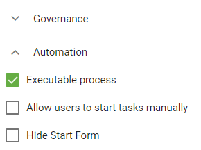
GBTEC Work Orchestrator is directly connected to GBTEC Process Design. Processes that are displayed and can be executed in GBTEC Work Orchestrator, have previously been defined as such in GBTEC Process Design. This can be done using the diagram attribute Executable process within the attribute group Automation of the diagram types Business Process Model and Notation (BPMN) and Event-Driven Process Chain (EPC). This checkbox has to be activated to declare the process as executable. How to display the attributes of a diagram is explained in this chapter.
In the productive environment of GBTEC Work Orchestrator, processes are usually only displayed as long as the corresponding diagrams in GBTEC Process Design are published. You can then see these processes in the ProcessApps. If you unpublish a diagram in GBTEC Process Design, you can no longer create new cases for the associated process. As long as running cases of this process still exist, the ProcessApp remains visible. If no running cases remain, the ProcessApp is removed from the overview. This currently also applies if archived cases still exist. If you make changes to a diagram, it must be published again for the changes to become visible in the associated process in the productive environment.
Hint
In the development und test environment of GBTEC Work Orchestrator, a process can already be tracked during its development. This reflects the modeling of the corresponding diagram in GBTEC Process Design.
Note
Note that access restrictions, defined in GBTEC Process Design, will also effect the visibility of processes in GBTEC Work Orchestrator. This means that diagrams which have an access restriction in GBTEC Process Design, will only be visible to you as a process in GBTEC Work Orchestrator, if you are part of the corresponding access restriction.
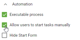
Additionally, ProcessApp Administrators have the option to determine whether other user groups are allowed to start tasks manually. To do this, the checkbox Allow users to start tasks manually can be activated. This enables the initiation of previously unstarted active segments of a task.
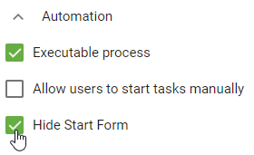
By selecting the option Hide Start Form, you can configure that when creating new cases for the process, you will be redirected directly to the process flow view, skipping the case start form. The new case will be named based on the process name and the timestamp.
ProcessApp Modeling
How can I configure my ProcessApp icons?
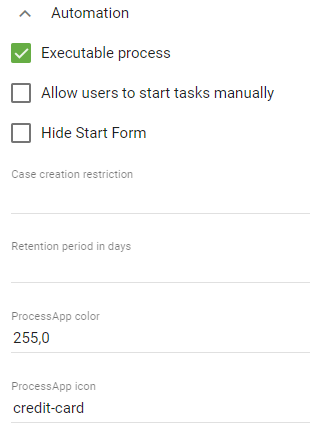
The icon used to display your process in the ProcessApp area in GBTEC Work Orchestrator can be customized in the attributes of the corresponding diagram in GBTEC Process Design. To configure an icon, navigate to the details of the relevant diagram in GBTEC Process Design. Here you will find the attributes ProcessApp color and ProcessApp icon under the attribute group Automation.
You can use the ProcessApp color attribute to specify the icon’s color. As value enter the RGB color code of your desired color, for example red via 255,0,0. You can also use HEX codes, such as #FF0000 for red, or the corresponding color names. The task icon is always the same color as the ProcessApp.
The icon can be defined via the attribute ProcessApp icon. You can choose an icon provided by Font Awesome (v6.5.1), which is available for free. Enter the name of the icon as the value of the attribute.
An example could be as follows:
The result will then be displayed like this:
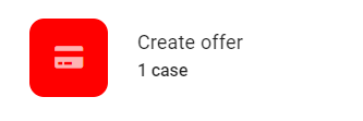
The default icon for undefined processes is a diagram icon.
Note
You can choose from all Font Awesome icons in version 5.15.4 except the trademark-protected ones.
How can I restrict the visibility of all cases in the ProcessApp?
If you want to restrict the visibility of processes within the ProcessApp section of GBTEC Work Orchestrator, you can do so during modeling. Navigate to the details of the regarding diagram in GBTEC Process Design. Here, under the Automation attribute group, you will find the Analyst attribute.
The Analyst attribute allows you to maintain multiple users or user groups that can view all cases within the ProcessApp after the process is published. It is important to note that users must be assigned to the ProcessApp Analyst role. All other users will only be able to see the cases assigned to them within the ProcessApp.
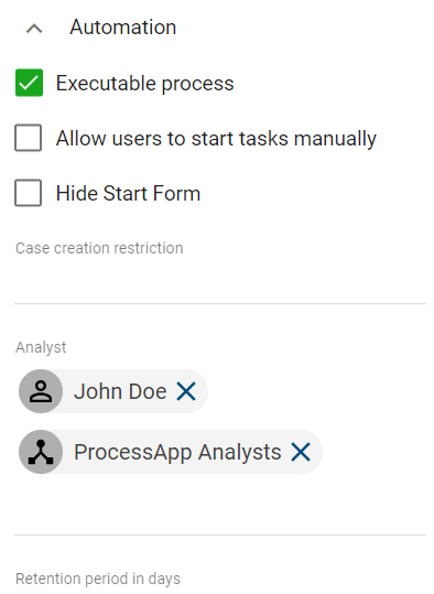
If you change the users or user groups in the Analyst attribute, previously maintained users and user groups will no longer have access to all cases within the ProcessApp.
How can I restrict access to a ProcessApp and its cases?
As a ProcessApp Creator, you have the option to restrict access to a ProcessApp and its cases. To do this, go to GBTEC Process Design, check out a diagram, and click an empty space on the canvas. Then, in the Details panel in the right sidebar, open the Governance attribute group. In the Restricted access field, you can enter users and/or user groups that have access to the process.
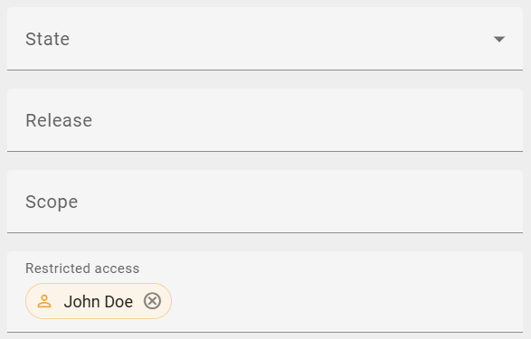
All unmaintained users and/or user groups will not have access to the modeled process and will not be able to initiate cases or view the associated ProcessApp.
Note
Users with the ProcessApp Administrator role can view access-restricted ProcessApps in both the ProcessApps area and in the Administration menu item. However, archived cases will not be shown.
How can I restrict access to the case flow view?
As a user with the ProcessApp Creator user role, you can restrict access to the flow view of cases. To do so, open a diagram in GBTEC Process Design, check it out, and click on an empty space on the canvas. Then, in the Details panel in the right sidebar, open the Automation attribute group. In the Access to case flow view input field, you can enter users and/or user groups who should have access to the flow view of the associated cases.
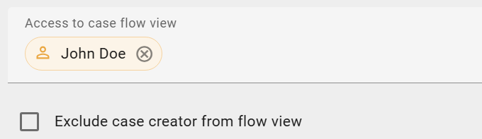
The maintained users will then have access to the flow view of both their own cases and those of other users. All users and/or user groups not maintained can only access the flow view of their own cases.
You can also enable the Exclude case creator from flow view option. When this option is enabled, users and/or user groups not maintained can only initiate cases for this process and work on its tasks. However, they will not have access to the flow view of any cases for this process.
After you have applied a restriction to the case flow view, you must check in and publish the diagram. The restriction only applies to initiated cases in the Publication stage.
Hint
Please note that maintained users and/or user groups are not affected by the access restriction when the Exclude case creator from flow view option is enabled, even if they have initiated their own cases.
Note
Please note that users with the user role Administrator can view the case flow view even if the view has been restricted by the ProcessApp Creator and the Administrator is not included in the maintained users and/or user groups.
Process Execution Editor
Form Editor
With the form editor, you can create the form of a user task. You can configure different form fields that will be displayed in the form of the task when the process is executed. The responsible of the task can fill the fields when completing the task.
How can I create and configure my own form?
In order to use the form editor, your diagram has to be marked as executable process in the attributes. The activity type of the task has to be User.
Now you can open the form editor. To do so first open the context menu of the activity with a right click on it. There select the entry Form Editor.
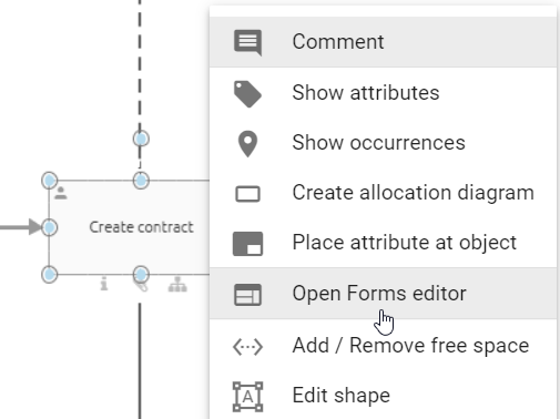
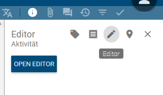
Alternatively, you can open the form editor via the options of a task. To do that, select the activity and open the options on the right side. There you can find the Open editor button in the Process Execution Editor option. Select this button and the form editor will open.
The form editor opens in a new dialog. On the left side of the form editor you will find all available form fields that can be added or configured. In the middle of the editor you can see a preview of the form which contains all elements that have already been added to your form. If one of those elements has been selected you can see its details on the right side of the dialog.
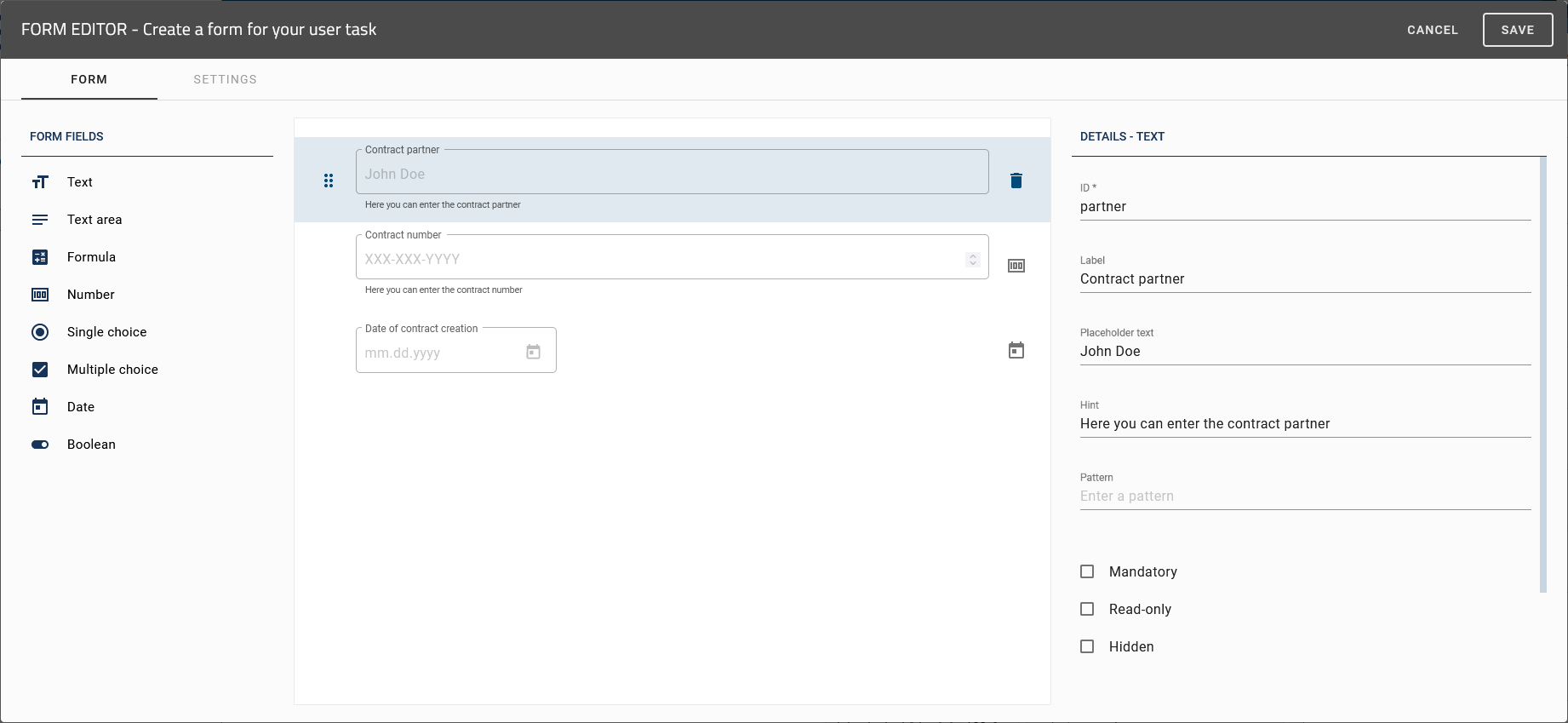
Within the form editor, you can add new elements to your form, adjust the position of the different form fields within the form, change their attributes, or remove single form fields from the form.
To apply your changes, confirm your entries by pressing the Save function in the top right corner of the form editor. By using the X icon located directly beside it, you can leave the form editor and the changes will be discarded.

As soon as you have saved your changes and the corresponding diagram meets all requirements to be displayed as a process in GBTEC Work Orchestrator, your form can be found in addition to the automatically generated form fields of the task.
Note
Please note that in order for your form to be editable in a case’s process flow, the appropriate task must be assigned to a user.
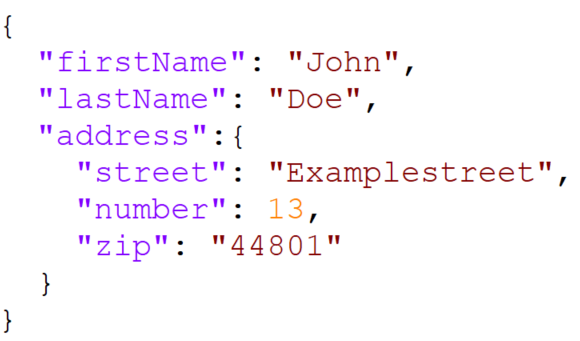
You can use process variables in your form. They need to be enclosed by two curly braces (e.g., {{variableName}}). If you received a data object via a rest call, you can use that as well in your form. The following example shows a JSON file with the data object ‘address’. To use the zip-code as a variable, you need to use address.zip. You can nest as many data objects as you like.
Hint
If a data object is named with a dot in the JSON file without a nested structure, it will be replaced with an underscore. In this example, if address.zip is not nested, the name will automatically be renamed to address_zip. After the replacement, you need to use the underscore(s) to continue using the variable(s).
Warning
Remember to also save the diagram, after you have applied changes within the form editor. Otherwise your changes will be lost when leaving the diagram.
Note
If you have errors in your task form, the form will not close after saving. You will see an error icon on fields with errors. After solving them, the task form can be saved and closed.
How can I create a start form?
As a ProcessApp Creator, you can create a start form using the form editor. To do this, you need to type the start event as a Message during modeling in GBTEC Process Design. You can find this option in the Details of the start event in the right sidebar.
You can then open the form editor by right-clicking on the start event and selecting the Form Editor option from the context menu. Alternatively, you can open the editor through the Process Execution Editor option in the Options panel in the right sidebar.
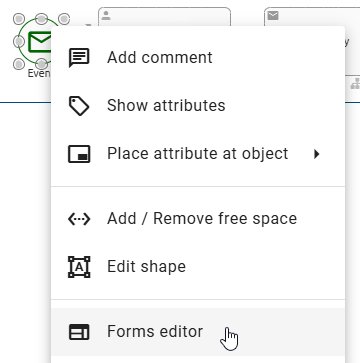
After clicking the option, the form editor opens. Here, you can configure your form by adding new elements and editing the field properties. This enables you to define relevant process information directly in the start form and start the process immediately.
Once you have saved your configured form and executed the process, your form will appear in the automatically generated task form in GBTEC Work Orchestrator.
To display the start form when creating new cases, the Hide Start Form option in the Details panel of the right sidebar must be deactivated. When you create a new case with a start form, it will be displayed as a user task. After filling out the form and clicking the Create button, a notification will appear in the lower right corner of the screen with a link to the corresponding case, allowing you to switch directly to the process flow.
If you cancel the creation of a new case using a start form, you will be redirected to the case list of the associated ProcessApp.
Hint
Please note that the start form can only be displayed if the process contains only one start event.
Warning
Please note that the File form field is not displayed in start forms with repetitive sections and is therefore not available in the task form in the process flow view.
How can I create an automatically generated form?
As a ProcessApp Creator, you have the option of creating an automatically generated form with the help of our AI assistant Arty. To do this, select the Diagrams menu item in the left menu bar in GBTEC Process Design and open a diagram from the desired repository. After opening, check out the diagram so that you can edit it. Then select an activity in the diagram and type it as a task type User in the Details in the right sidebar. You can then open the form editor by right-clicking on the selected activity or using the Process Execution Editor in the Options in the right sidebar.
If the AI-supported functions of Arty are activated for you and no form exists yet for the activity, the form editor offers you the option of having a form created automatically. Before the form is generated, you will see an input field that can be prefilled based on the description of the activity. This input field serves as the basis for the AI and can be freely customized. You can find out how to best communicate with Arty here. Once you have confirmed the input, click on the Generate form button to start the creation process.
As a ProcessApp Creator, you also have the option of using the Upload image button to upload a file containing the information that you want to store in the process later on. Arty automatically recognizes the data contained in the file and transfers it to the form fields.
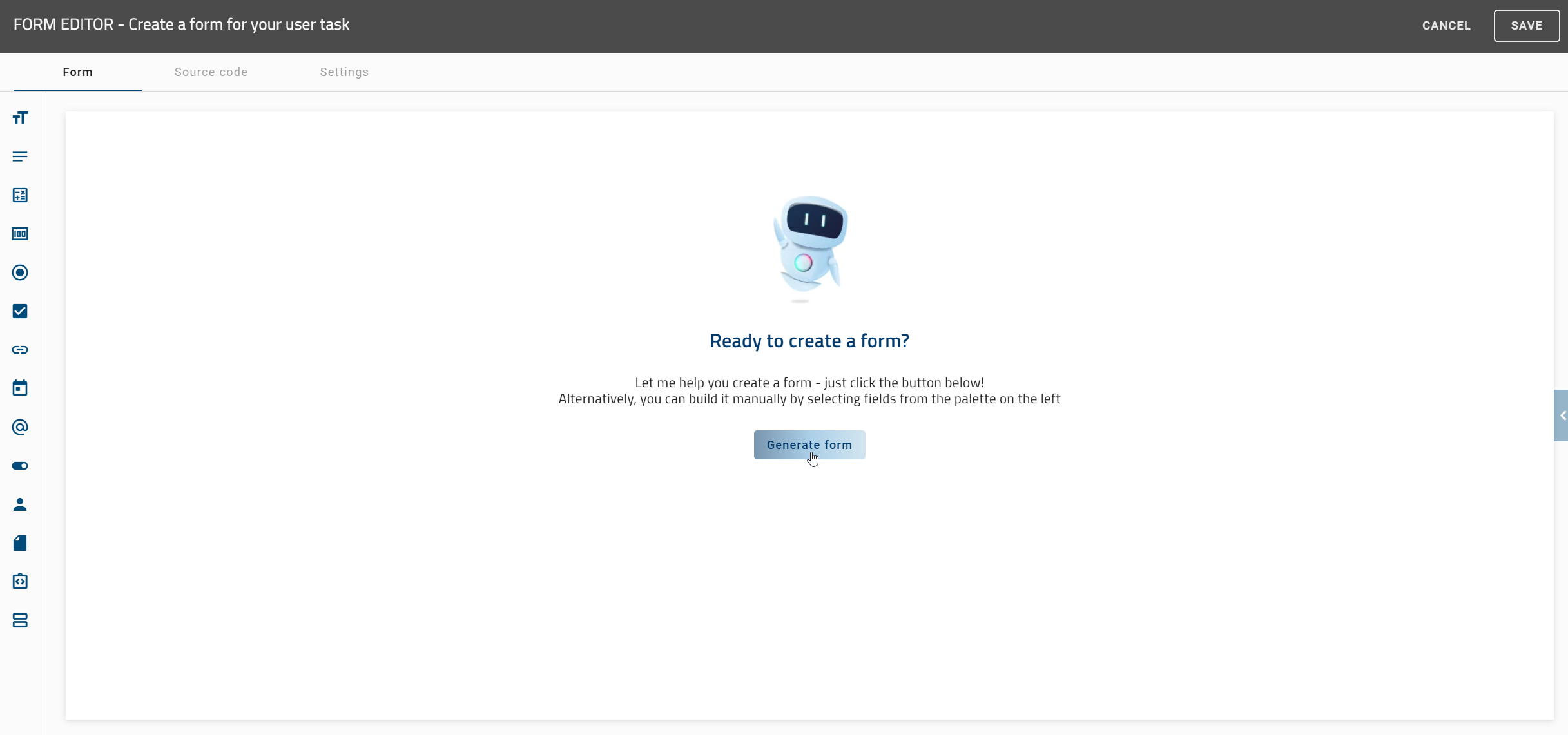
Your request will then be processed and you will receive the automatically generated form within a short period of time. Here, you can make further changes, such as adding relevant process information or rearranging the position of individual form fields.
Finally, save your form by clicking the Save button in the top right corner. To discard the form, click on the X icon located directly beside it.
Tip
You also have the option of automatically linking form fields to existing process variables. Arty recognizes process variables that already exist in the process variable list and, if desired, automatically inserts them into the current form. The selection or instruction is made directly in the chat, so no manual assignment is necessary. Existing variables are reused, and new variables can be generated automatically as needed.
Hint
Please note that the AI-supported features of Arty are not included in the standard license. Please contact your representative for more information. Please also refer to the notes on using the AI feature.
Tip
To generate a more accurate form for your process, we recommend that you provide the relevant information in the description of the activity.
Which form fields exist and how can I add a new form field to my form?
You have the possibility to add these form fields into your form:
Variable List: A list of all variables you have created to display and add existing process variables as form fields so that you can reuse them without redefining them.
Text: A simple text field for the in- and output of alphanumeric strings.
Text area: Text field for the input of longer text such as descriptions and comments, which also allows formatting the text.
Formula: Formula for calculating numeric or logical values.
Number: Field for the in- and output of numeric values. Can store numbers with decimal places.
Single choice: Choice field where a user can choose exactly one option of several predefined options. This can be configured as a list or drop-down menu.
Multiple choice: Choice field where a user can choose one or more options of several predefined options. This can be configured as a list or drop-down menu.
Date: Field for the in- and output of dates.
Boolean: Field with a binary decision.
Email: Field where a user can enter an email address or get an email address as output to write an email.
URL: Field for the in- and output of web addresses.
Users/User groups: Field to add a user or user group.
HTML: You can use the HTML field to display clear and helpful instructions to help you fill in the form. These include text formatting, integrating links and the use of simple HTML tags.
File: Field to upload files.
Section: Field to define the arrangement of multiple columns in a form.
To add a new form field into the form, first open the form editor at the corresponding activity. In the left sidebar, select the desired form field that you want to add to your form.
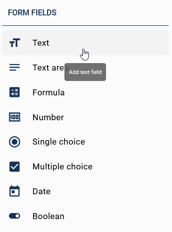
A new entry will be created at the bottom of the form preview. If you select the new entry you can edit the form field according to your needs. Every form field has different attributes which are explained in the following sections. Alternatively you have the option to add a form field via drag & drop into the designated position.
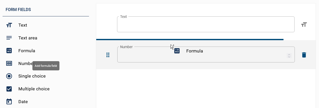
The field will be inserted underneath the blue line.
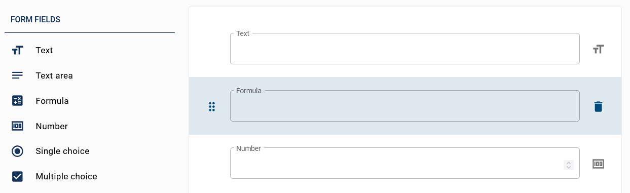
Which attributes does a form field have?
With attributes, you can configure your form fields in the right sidebar individually. For every form field there is a set of commonly available attributes:
ID: If you add a new form field it automatically gets an ID. This ID is available as a process variable in your process and is necessary if you want you can change the ID of your form field. This can be helpful if you want to use your input again. Furthermore you have the option to use already existing process variables as ID’s. In this way you can get the current value of the corresponding variable in your process.
Label: With the label you enter a name for your form field which will be displayed to the user in the form field at the top left.
Placeholder text: Here you enter a text which explains what kind of input is expected (for example, a short description or an example).
Mandatory: If this checkbox is activated, the user needs to make an input before being able to continue.
Read-only: If this attribute is activated, the user cannot change the value of this variable. This is recommended if you only want to output a value.
Hidden: This attribute can be used, if you do not want the user to see the form field. When a field is Hidden, no validations (e.g., mandatory, minimum length, etc.) are performed.
Repetitive: [Only for the “Section” form field] When this attribute is activated, the configured section field repeats as many times as defined when the process is executed.
Hint: This attribute can be used to display a hint below the input field for the user.
Default value: This attribute can be used to define a default value. You can decide whether you use a value or a formula that needs to be evaluated. Process variables must be enclosed by two curly braces.
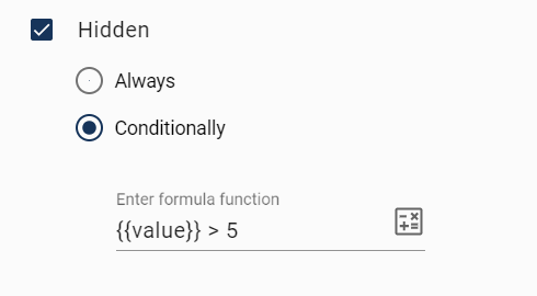
With some attributes you have the possibility to choose whether they should always behave as specified or just in some cases. You have this option on the form fields Hidden, Mandatory, and Read-only. There are two different options possible for this. Always ensures that the corresponding form field always behaves as specified. Conditionally lets you type in a formula which decides whether the attribute is applied or not.
In the following screenshot you can see an example where the field will be Hidden if the variable value is bigger than 5.
After editing the attributes you can confirm your changes by using the function Save.
Note
Please note that the values of the properties apply to all content languages and cannot be defined individually for each.
The following sections explain which additional attributes each form field has.
Variable List
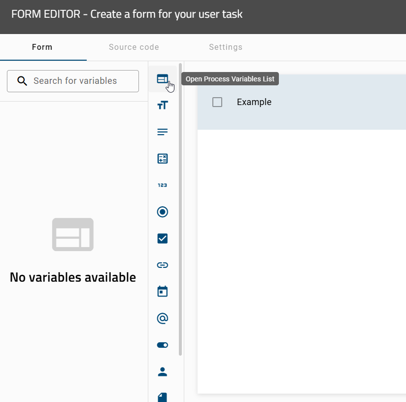
As a user with the ProcessApp Creator role, you can directly access the list of available process variables in the form editor. Clicking the Open Process Variable List icon opens a side panel displaying all unused variables in alphabetical order. At the same time, the details view in the form editor automatically closes.
Each variable displayed in the list can be used as a form field and added to the form by clicking or dragging and dropping it. Once a variable has been added, it appears grayed out in the list and can no longer be added again. However, if the ID of the variable is changed within the form, it becomes available again in the list. If multiple variables share the same ID, only one instance of that variable is displayed in the list.
Using the search field above the variable list, you can search for specific variable names. While typing, the list updates automatically in real time, showing only the variables whose names match your input.
Note
Please note that Arty does not interact with the list of process variables.
When you create a Section and assign at least one ID or label to it, that section is automatically added to the list of process variables.
You can use not only entire sections but also individual fields within a section. When you expand a section in the process variable list, you see the fields it contains, for example: street, streetno, and city. If you select one of these fields or drag it into the workspace, only that field is added to the form, not the entire section.
Text field
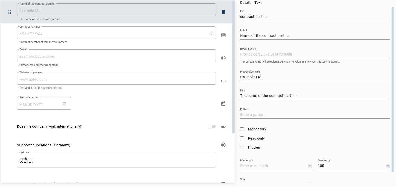
The simple text field can be used for the in- and output of short alphanumeric strings.
It has the following additional attributes:
Pattern: Enter a regular expression the input must match in order to be valid.
Size: This value indicates how wide the input field is (measured in characters).
Min length: This value defines the minimum of characters needed to make a valid input.
Max length: This value defines the maximum of characters needed to make a valid input.
Hint
An example for a pattern could be ([a-z]\d\d)+. This regular expression indicates that a combination of a lowercase letter followed by 2 digits is valid. Those can be repeated several times. An example for a valid input would be a14b22 or q41c96b74e44. Other inputs like A54b41 or 1d23 would not be valid.
The basics of a regular expression are demonstrated below:
A regular expression (RegExp) is a pattern that is searched for in character strings.
Syntax:
/pattern/flagsPattern: The character string that is being searched for.
Flags: Modifiers such as
g(global),i(ignore case),m(multi-line).
Permitted patterns:
Character classes:
.: Any character except line break\d: digit (0-9)\w: Alphanumeric character and underscore\s: White space character (space, tab, etc.)
Groupings and alternatives:
(...): Grouping|: Or operator
Quantifier:
*: 0 or more+: 1 or more?: 0 or 1{n}: Exactly n{n,}: At least n{n,m}: Between n and m
Anchor:
^: Start of the input$: End of the input
Examples:
^\d{5}$: Five-digit number^(https?|ftp)://: URL that starts with http, https or ftp^[a-zA-Z]+$: Only letters (upper and lower case)
The following links allow you to view details about the RegExp class used, which the browser uses in the background for pattern checking, as well as the corresponding online tester for RegExp:
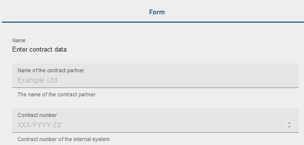
In a running case, the text field above results in:
Text area field
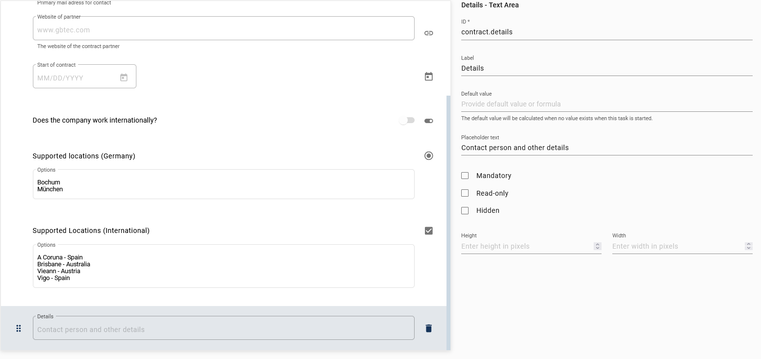
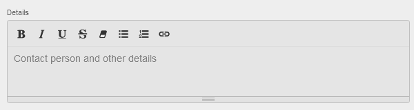
The text area field can be used for longer alphanumeric strings. For example, it could be used to save or show descriptions or comments. It also allows to format the input (e.g. bold, italic, etc…).
It has the following additional attributes:
Height: This value indicates how high the text area is (measured in pixels).
Width: This value indicates how wide the text area is (measured in pixels).
In a running case of the example above, the text area is displayed as follows:
Formula field
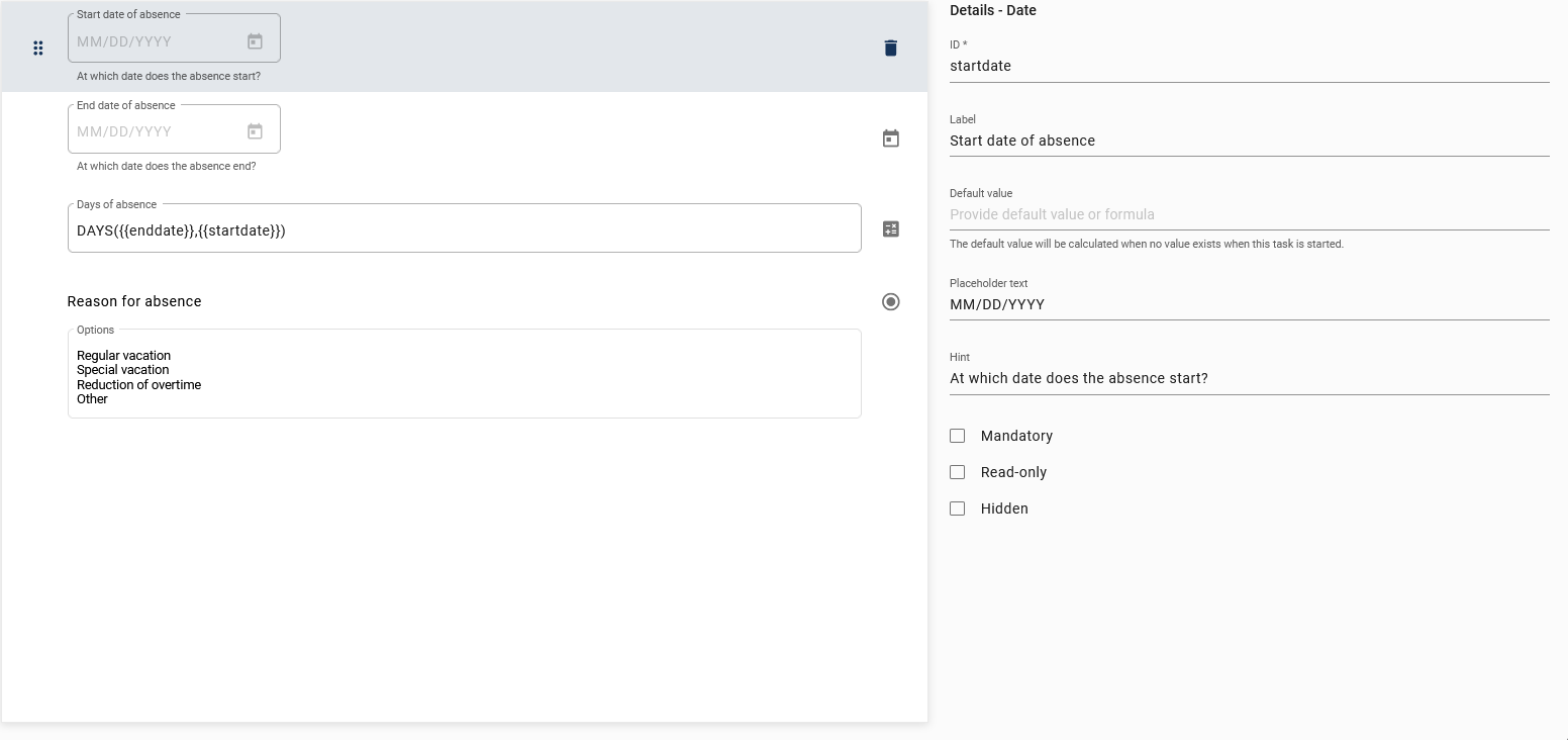
The formula field can be used to calculate a variable. It can be a numeric or logical value, even calculations with date values are possible. You can get an overview of all available formulas in this chapter.
It has the following additional attribute:
Formula: Here you select the formula you want to use. Possibly one or more parameters are necessary to calculate your formula.
Note
Please be aware that the attribute read-only is always active for the formula field.
When entering your formula, you must pay attention to the following:
The formula needs to be written in capital letters.
Parameters have to be in braces and need to be separated by a comma.
If you want to use earlier defined process variables, you need to put them between two curly braces (e.g.,
{{VariableName}}).Other parameters do not need to be enclosed by curly braces.
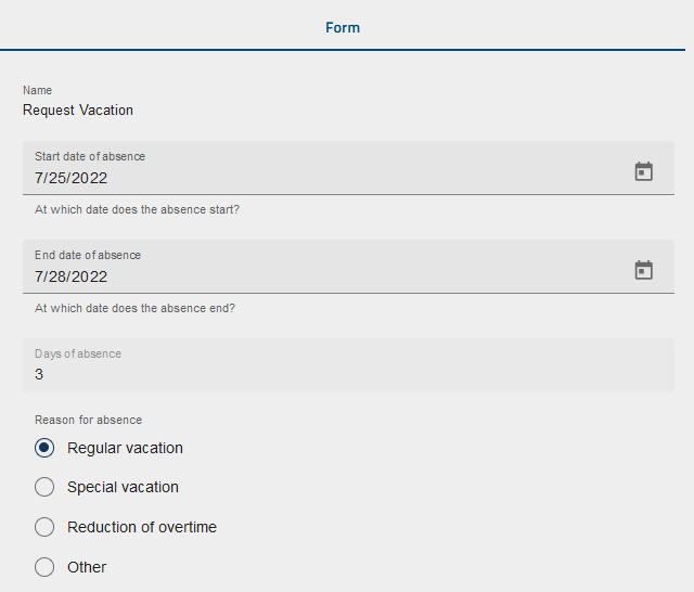
In the example above, the formula computes the number of absence days. This is done in a running case as soon as both start and end date have been entered:
Number field
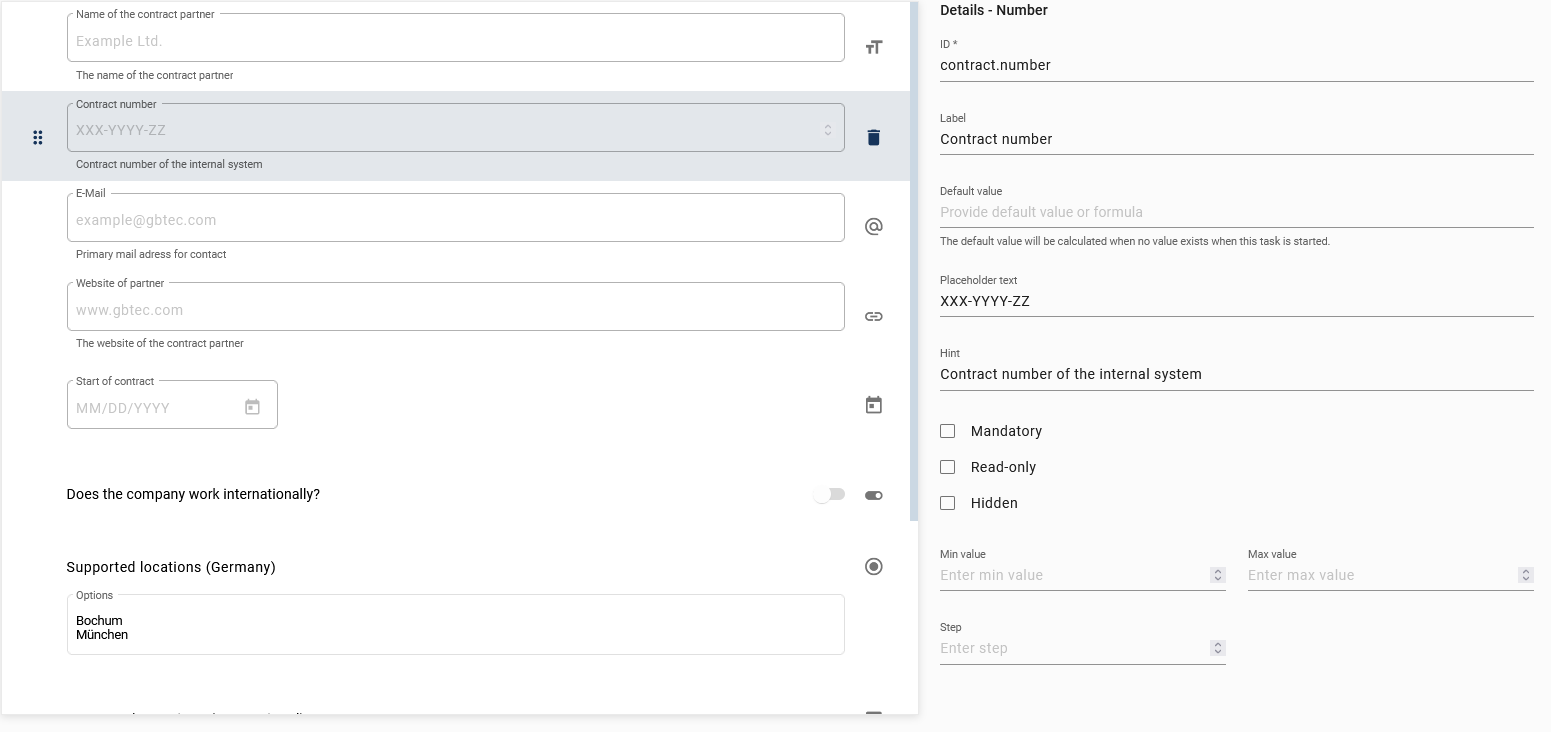
The number field can be used to save or show numeric values. The use of decimal numbers is also possible.
It has the following additional attributes:
Min value: Enter a value here which is the lower limit for the user input.
Max value: Enter a value here which is the upper limit for the user input.
Step: This value defines by how much the input value increases or decreases when using the input form. The standard step is 1. Regardless of the step size, the user can enter their own values as long as they are between the min and the max values.
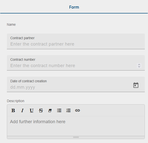
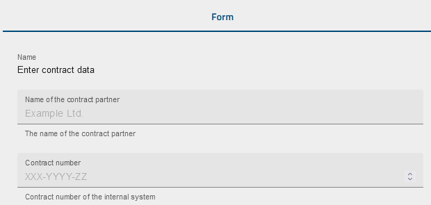
In the example above, the attributes min and max value of the number field “Contract number” are maintained in such a way that the user must specify a four digit number.
Single choice field
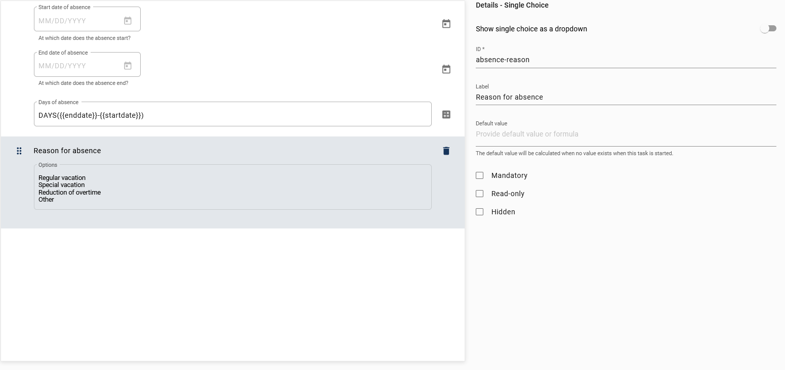
The single choice field can be used when the user needs to choose exactly one of several predefined options.
It has the following additional attributes:
Options: A list of available options from which the user can choose. The options are separated by a line break.
Show single choices as a drop-down: If you activate this attribute, the user can select the desired option from a drop-down menu. These can be selected with a mouse click or entered manually. When the user makes an input, the number of choices is reduced to match the input. If the input does not match any option, no options are displayed. Deactivating the attribute will lead to a presentation of the options in a list.
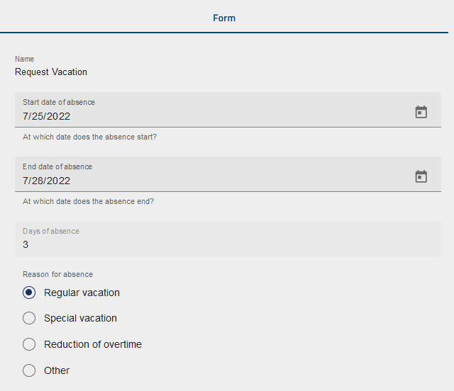
The single choice field “Reason for absence” in the example above is configured as a drop-down menu. In the following, the option “vacation” has been chosen:
Keys
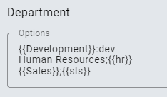
You can define a key for each option that is stored as the value of the process variable instead of the actual option. You can add the key to the respective option using a semicolon as separator. If an option itself contains semicolons, the last one is detected as separator. For example, the form field “Department” will have the option-key pairs Development - dev, Human Resources - hr and Sales - sls:

If the option Development is selected by a user in a case, the process variable “Department” is saved with the value "dev".

You can also make the selection options dynamic. In this case, the options can come from process variables that can change.
The {{…}} notation is used as a placeholder and is replaced by the value of the corresponding process variable.
If the value of the process variable used as a placeholder is a comma-separated string, the string is split by the comma. Each split element is then displayed as an independent option that can change depending on other variables.
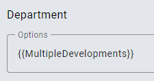
In this example, {{MultipleDevelopments}} is specified as an option, which is a comma-separated string. The task form now displays all the options contained in the process variable.
Warning
Please note that selection fields with multiple selections should not contain duplicate or identical entries. If, for example, the same key such as "EU" is listed several times or different selection options such as "Germany;EU", "Austria;EU" and "Spain;EU" are internally assigned to the same key, this can lead to unexpected behavior. To ensure correct use, all selection options should be clear and distinguishable from each other.
Tip
Keys can also be defined for dynamic options using a semicolon. As with static options, the key associated with the selected option is stored as a process variable.
Multiple choice field
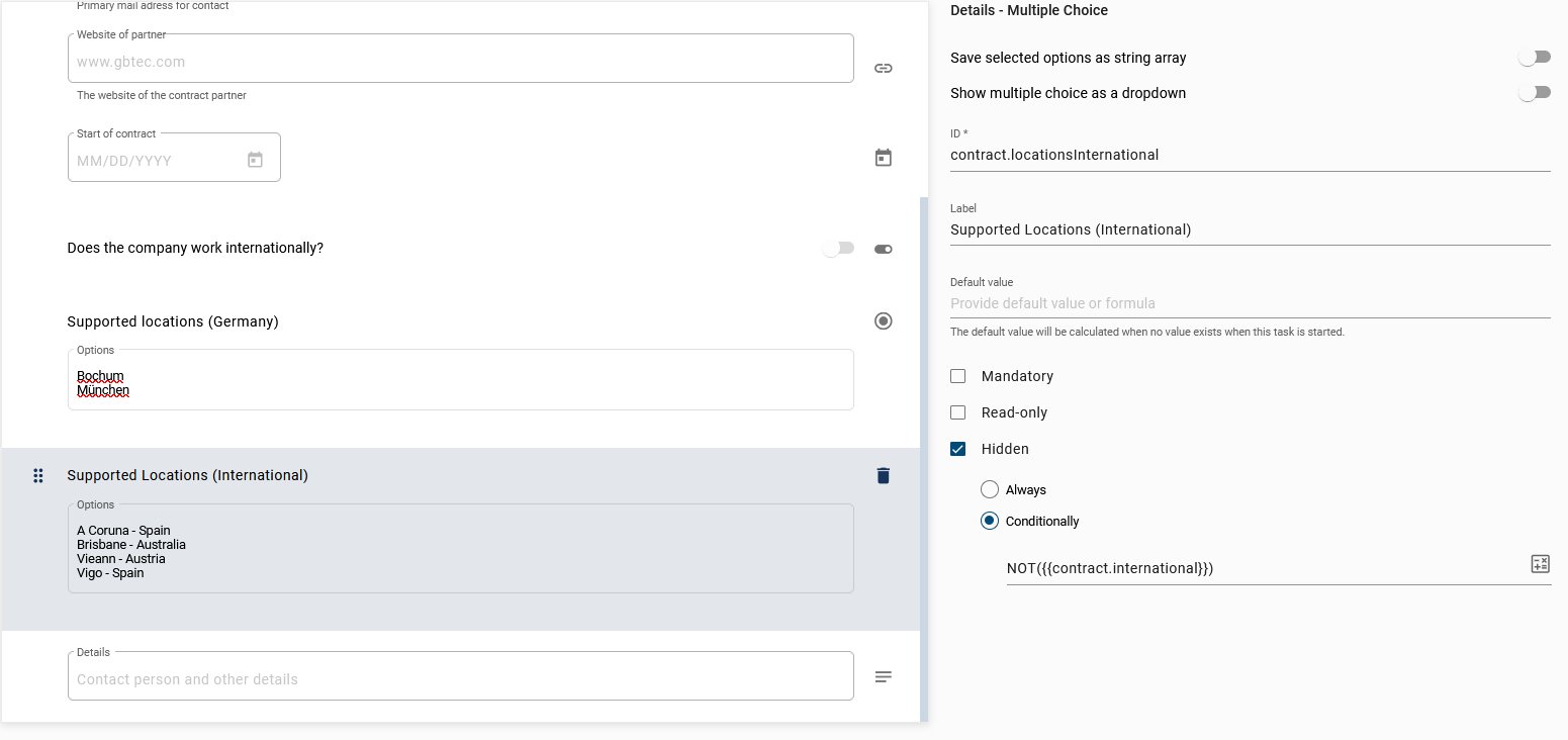
The multiple choice field can be used when the user can or needs to choose one or more of several predefined options.
It has the following additional attributes:
Options: A list of available options from which the user can choose. The options are separated by a line break.
Show multiple choices as a drop-down: If you activate this attribute, the user can select the desired option in a drop-down menu. Deactivating the attribute will lead to a presentation of the options in a list.
Save selected options as string array: This attributes indicates whether the process variable is saved as a string or as a string array. If you deactivate the attribute, the process variable is saved as a string. If you activate the attribute, the process variable is saved as an array of strings. The array contains the selected answers. Note that you can define keys that are stored in the process variable array. You can find an explanation below the next screenshot.
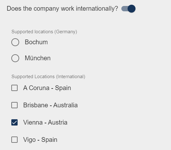
The multiple choice field “Supported Locations” above is only visible in the form if the process variable contract.international has the value TRUE. The process variable can be set to TRUE via the boolean field “Does the company supply internationally?”. In a running case, the fields are displayed as follows:
Keys
If you activate the attribute Save selected options as string array, you can define a key for each option that is stored in the string array instead of the actual option. You can add the key to the respective option using a semicolon as separator. If an option itself contains semicolons, the last one is detected as separator. For example, the form field “Department” will have the option-key pairs Development - dev, Human Resources - hr and Sales - sls:
Note
Please note that this attribute defines whether the process variable is stored as a single string or as an array of strings. If the attribute is deactivated, the process variable is stored as a string. If the attribute is activated, the process variable is stored as a string array containing the selected answers. Additionally, you can define keys that are stored within the string array.

If the options Development and Human Resources are selected by a user in a case, the process variable “Department” is saved with the value ["dev", "hr"].

You can also make the selection options dynamic. In this case, the options can come from process variables that can change.
The {{…}} notation is used as a placeholder and is replaced by the value of the corresponding process variable.
If the value of the process variable used as a placeholder is a comma-separated string, the string is split by the comma. Each split element is then displayed as an independent option that can change depending on other variables.
In this example, {{MultipleDevelopments}} is specified as an option, which is a comma-separated string. The task form now displays all the options contained in the process variable.
Warning
Please note that selection fields with multiple selections should not contain duplicate or identical entries. If, for example, the same key such as "EU" is listed several times or different selection options such as "Germany;EU", "Austria;EU" and "Spain;EU" are internally assigned to the same key, this can lead to unexpected behavior. To ensure correct use, all selection options should be clear and distinguishable from each other.
Tip
Keys can also be defined for dynamic options using a semicolon. As with static options, the key associated with the selected option is stored as a process variable.
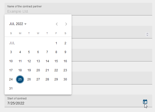
Date field
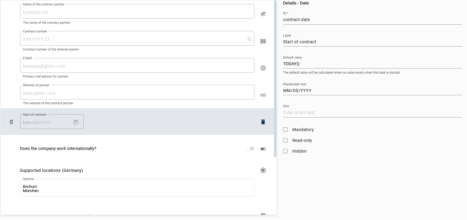
The date field can be used when the user needs to enter a date or display a specific date.
In the example above, two date fields are shown to the user. The desired dates can be selected from a drop-down calendar:
Boolean field
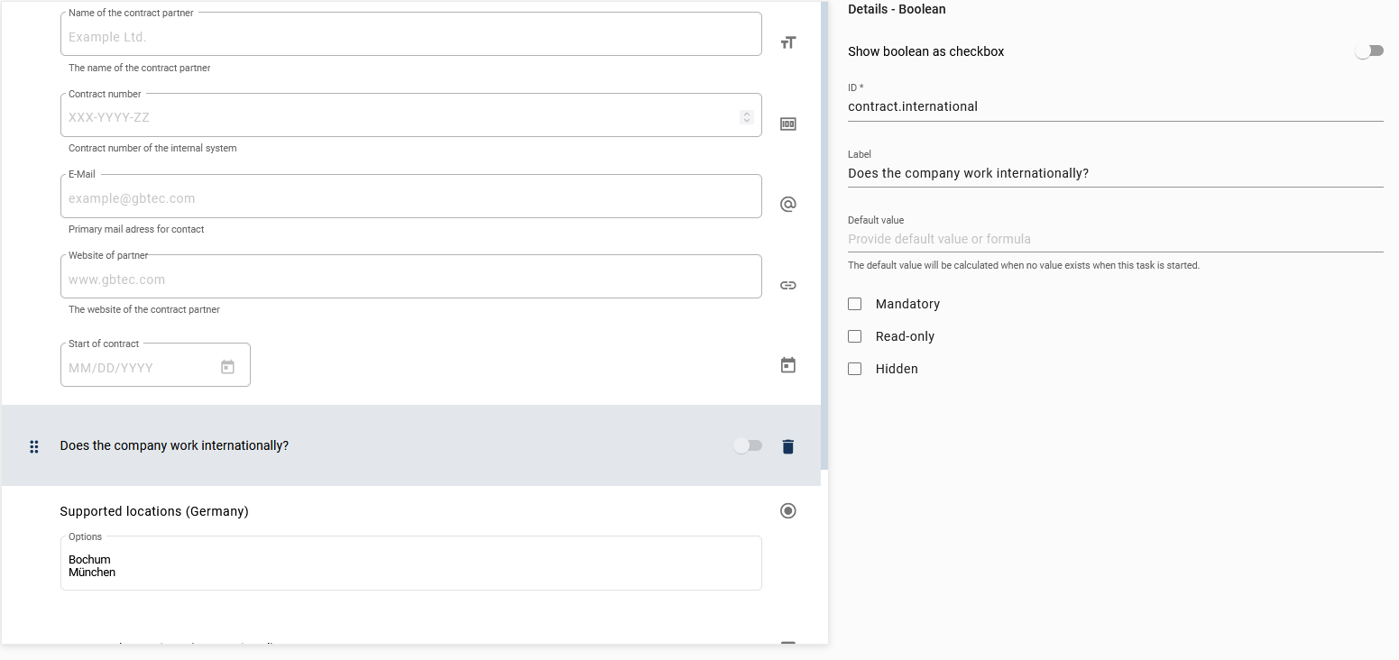
The boolean field can be used for binary (yes/no) or logical (true/false) decisions.
It has the following additional attribute:
Show boolean as checkbox: The appearance of the field will change and it will be displayed to the user as a checkbox instead of a toggle switch.
In the example, the checkbox is activated for the boolean field. It is displayed in a running case as follows:

Note
If you mark a boolean field as mandatory, users must check this field during a case in GBTEC Work Orchestrator to proceed with their case. If they are not doing that, an error message will appear to inform users that they need to complete the task to proceed further.
Email field
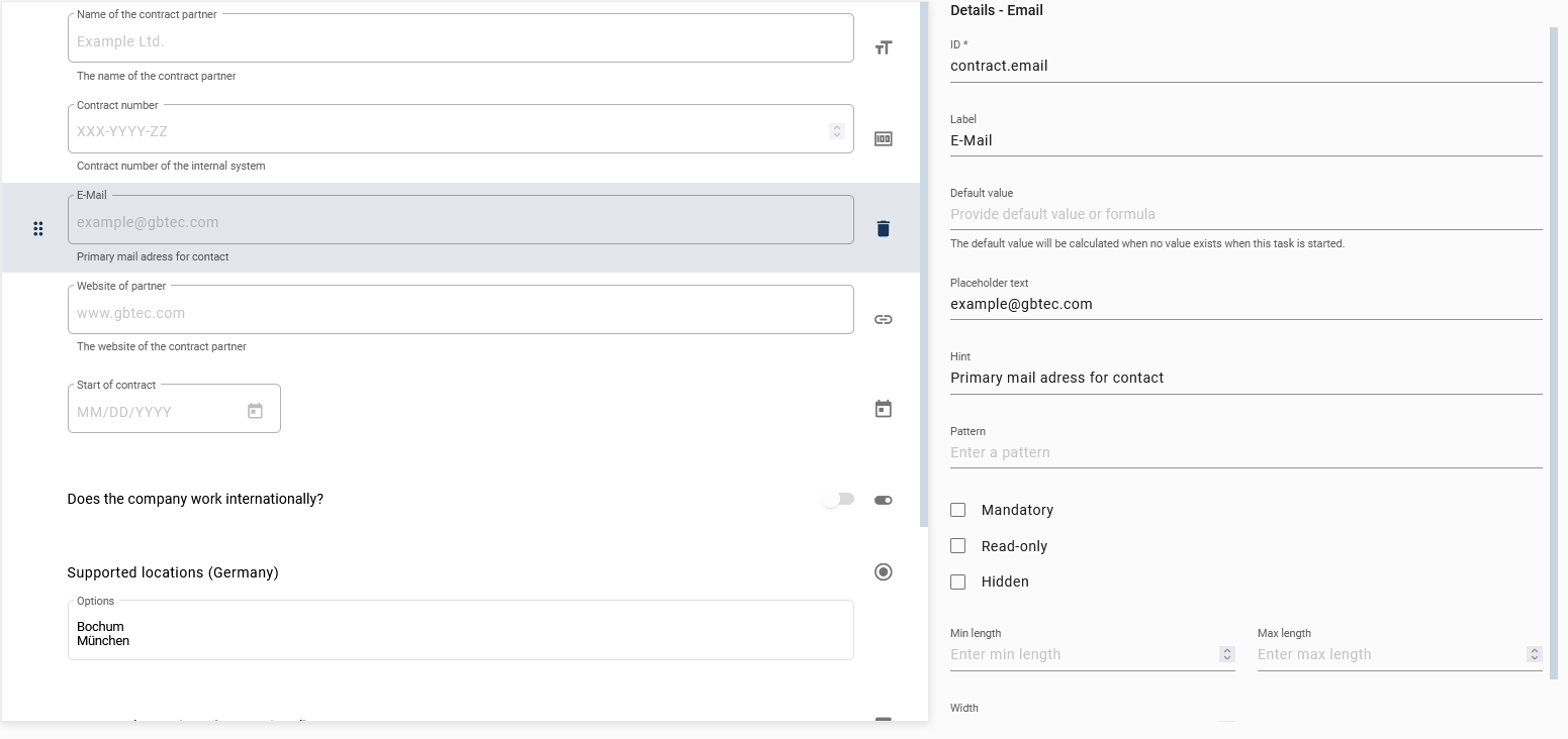
The email field can be used to input or display an email address.
It has the following additional attributes:
Pattern: Enter a regular expression that the input must match in order to be valid. If you do not enter a custom pattern, a standard pattern will check if the input matches an email address.
Min length: This value defines the minimum of characters needed to make a valid input.
Max length: This value defines the maximum of characters needed to make a valid input.
Width: This value indicates how wide the email field is (measured in pixels).
In the following example you can see an email field with the option Read-only activated. In that case the email address will be displayed as a link. When you are selecting the link, you will be redirected to your mail program, where you can send an email.

URL field
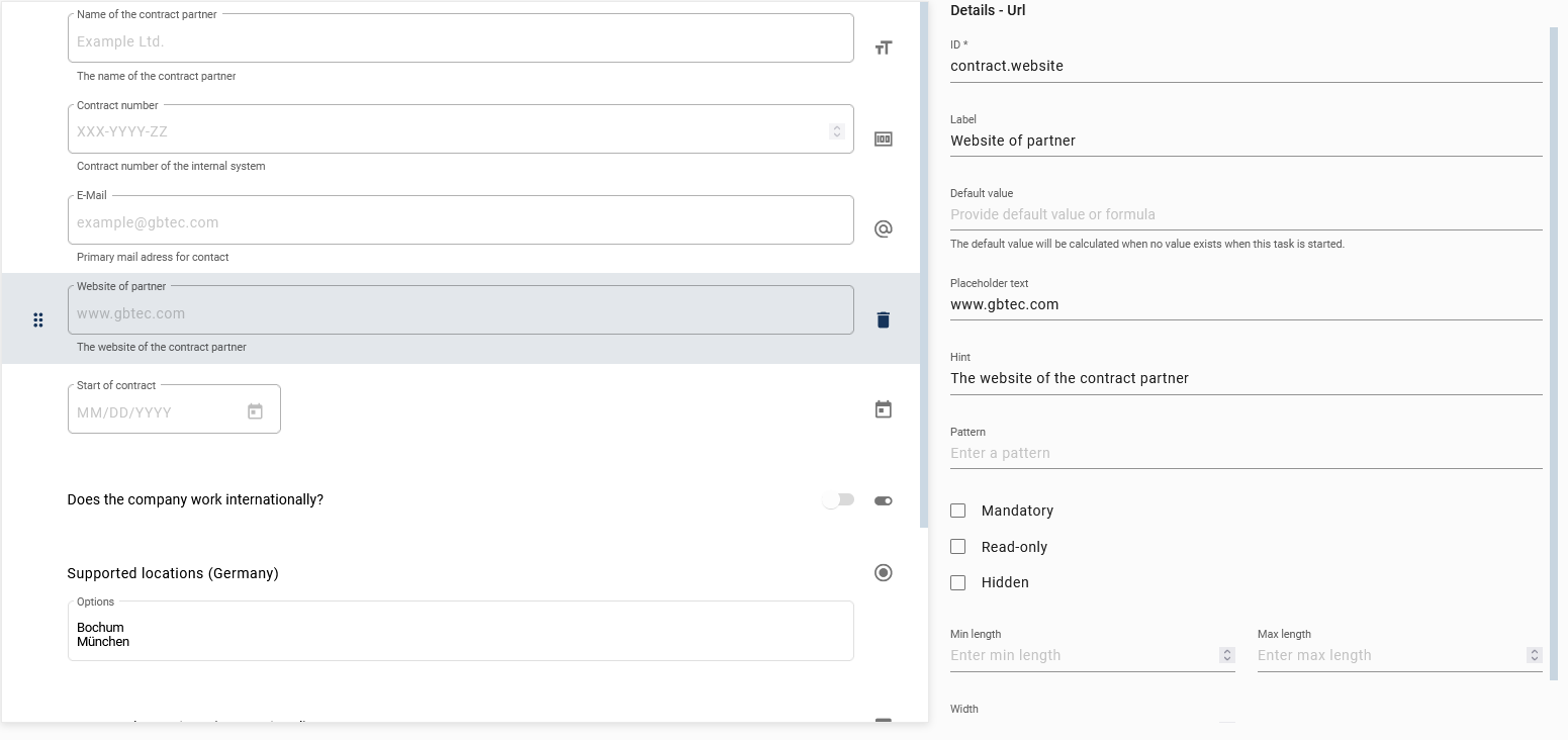
A URL field can be used to call or enter a web address.
It has the following additional attributes:
Pattern: Enter a regular expression that the input must match in order to be valid. If you do not enter a custom pattern, a standard pattern will check if the input matches a URL.
Min length: This value defines the minimum of characters needed to make a valid input.
Max length: This value defines the maximum of characters needed to make a valid input.
Width: This value indicates how wide the URL field is (measured in pixels).
In the following example, you can see a URL field with the option Read-only activated. In this case, the web address will be displayed as a link. When you select the link (Ctrl + mouse click), it will open in a new tab in your browser.

Users/User groups
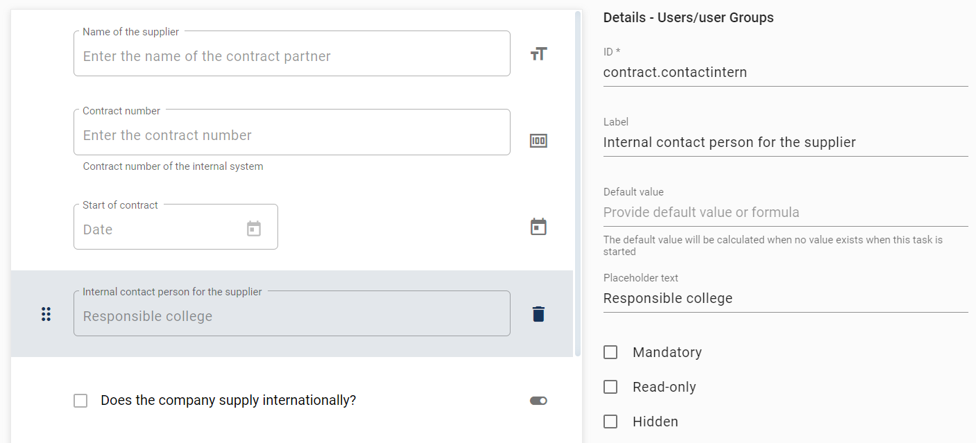
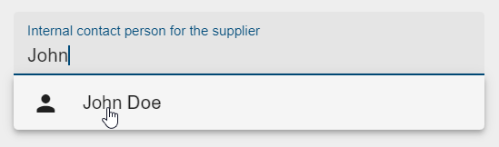
A Users/User groups field can be used to enter a user or user group to be included in the case. Note that you can only add one user or group to a Users/User groups field. If you start to enter a value in this field, a list of suggestions appears from which you can select a user (group). In the case of a user, the email address is stored as a process variable, and in case of a user group, the name is stored.
Version 7.17.0 now provides additional user information as a JSON object for users and user groups. This JSON object includes the user’s ID, name, email, and whether it represents a single user or a user group. To access individual user information, use the assigned ID of the Users/User Groups form field as a process variable and retrieve the corresponding value.
Example:
You have added the Users/User Groups form field to the form and set the form field ID to employee. The JSON object for the user will now be generated as follows {"id": "employee", "name": "John Doe", "email": "jd@gbtec.com", "type": "ProcessApp Participant"}. To access the individual information, you can access the variables as follows:
.name
.email
.type
Now you want to retrieve the user’s email. To do this, use employee.email. In this example, the result is jd@gbtec.com.
If the ID of the form field is the same as the identifier attribute of a role in the process, then this role will be linked to the form field. This means, that the initial value of the form field will be the user (group) that occupies the role in the current case. Also, if a new user (group) is set in the form field, this user (group) will occupy the role after the corresponding task is completed.
You also have the option to restrict access to specific user groups. To do this, enter the desired groups in the Restrict to user groups input field, where they will be stored and displayed as chips. During process execution, only users who are members of one of these groups can be selected. This ensures that only members of the designated user groups are considered for executing the process.

File
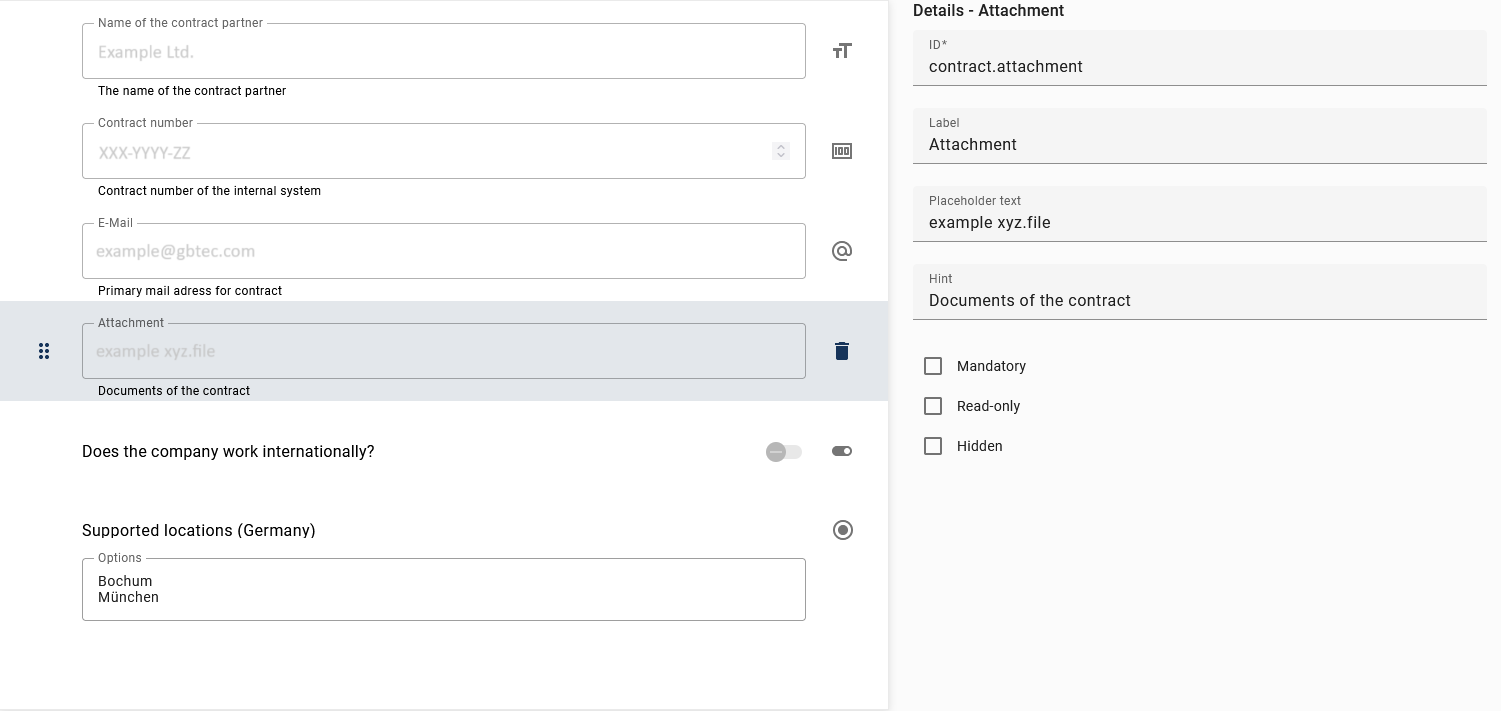
The file field can be used to upload files and embed them in the process.
Note
Please note that the form field and the associated document must have the same identifier for the form field to work. The document then represents either the input or the output document.
If you define a form field as read-only and the input document is linked to the same identifier as the form field, the actions of that input document are applied to the read-only fields. A form field that is not read-only allows data to be entered, while a conditionally read-only field is editable under certain conditions.
If an output document has the same identifier as a form field, the actions of that document are applied to the field. If multiple documents have the same identifier, only the actions of the document whose identifier is displayed in the form field are visible.
If you are using a form with a file upload option, and you have selected a file to upload, a visual representation of the file name of the uploaded file is displayed. This makes it easier to identify the uploaded file in the context of the upload process.
Note
You have the option to use the same file field for both input and output documents. If both the input and the output have the same identifier as the form field for files and only the input contains a document, you can use the file field to download the input file. Conversely, if the output contains a document, you can use the file field to download the output file.
In addition, you can define which file types are allowed to be uploaded for the file field. To do this, enter the allowed files types in the File types input field.
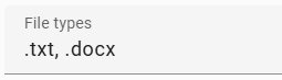
You can enter either one or multiple file types. If you want to specify multiple file types, they must be separated by a comma. Please note that only files with the specified file types are allowed to be uploaded. Furthermore, by entering image/*, you can allow the upload of all image files (e.g., .jpg, .png) or by entering text/plain, you can allow the upload of all text files.
Note
The File types input field accepts a wide variety of MIME types or file extensions. For a better overview of commonly used MIME types, you can find more information here
Additionally, you have the option to view uploaded PDF files in the integrated browser PDF viewer by clicking on the Download button. If an uploaded file is not supported by the PDF viewer of your browser, the file will be downloaded directly.
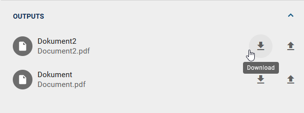
The above field for a file is prepared in the following way in the current process:

As a ProcessApp Creator, you also have the option of enabling photos to be taken via the device camera or uploading image files directly in the file field. An additional setting Enable camera capture is available for this in the file field field type.
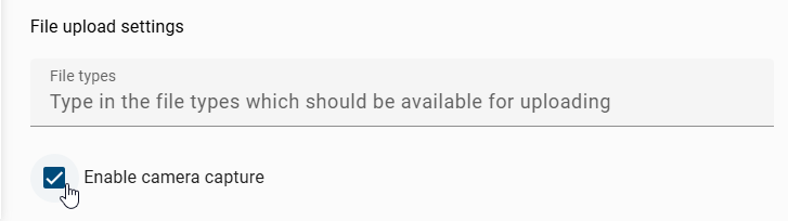
If you activate this option, you can take a photo within the form or select an existing image from your gallery.
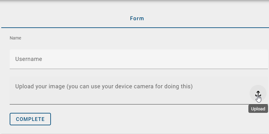
When you submit the form, the captured or uploaded image is saved and transmitted together with the other form data.
Tip
On mobile devices, a camera icon is displayed next to the upload icon if the device has a camera. If you tap on this icon, the device’s camera function opens and the photo taken is automatically added to the form. Alternatively, you can still select an existing image file from your gallery.
Note
Please note that the camera function is usually not available on desktop devices. In this case, no camera icon is displayed. Instead, you can use the file upload icon to select an existing image file from your computer. The upload works as usual without an error message being displayed.
As a user with the role ProcessApp User, you can use the File field within repeating sections of a form. This allows you to upload one or more input documents for each repetition and to reliably reuse these files in subsequent tasks. You can also link multiple input documents to a single activity, enabling you to upload several files at once.
Note
Please note that if a File field is placed within a repetitive section and you upload a file in multiple repetitions, each of these files is stored separately.
Tip
In later tasks, you can access each uploaded file individually. You can also see at any time how many files have been uploaded in total. Each file remains uniquely assigned to its respective repetition, ensuring that the relationship between the other input data and the uploaded file is maintained.
Note
Please note that even if the file upload is marked as Optional, the behavior remains unchanged.
For a successful implementation, you must assign an identifier to the corresponding file. The document identifier consists of the identifier of the Section and the identifier of the contained File field. Both identifiers must be separated by a period.
Example:
If the repetitive Section has the identifier customerData and the contained File field has the identifier contract, the complete identifier for the input document is customerData.contract.
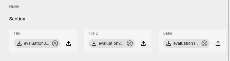
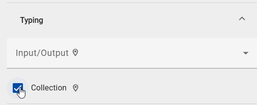
To ensure the function works correctly, the Collection checkbox must be activated for the corresponding document. To do this, open the Details panel in the right sidebar and switch to the Typing tab. Then click the Collection checkbox to activate it. The function is fully available only after this setting has been applied.
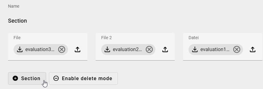
In the executed ProcessApp, you can add an additional section using the Section button and assign further documents to this section.
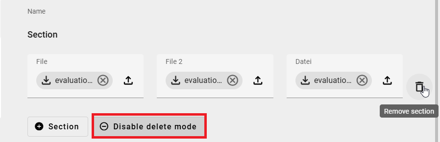
You can start deleting a section by clicking the Enable delete mode button. Then click the trash can to the right of the Section to delete it. To exit delete mode, click the Disable delete mode button.
HTML
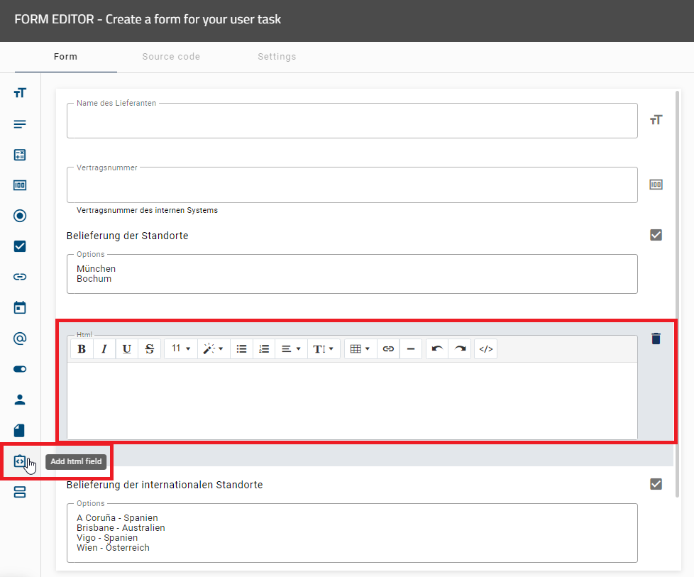
The HTML field can be used to display clear and helpful instructions in a form. This includes text formatting, adding links, and using simple HTML tags.
For example, if you use the HTML text <p>Welcome, {{first_name}} {{last_name}}! Please check the information carefully.</p>, the content is displayed in the preview of the form editor. When the form is executed, the placeholders {{first_name}} and {{last_name}} are automatically replaced with the corresponding process variables.
As a user with the user role ProcessApp Creator, you can retrieve task attributes directly within a task. To do this, use the getAttribute() function within an HTML field in a form. This function returns the value of a specific attribute, for example the task description using getAttribute("AT_DESCRIPTION"). To retrieve an attribute in a specific language, you can specify the language, for example: _task.getAttribute("AT_DESCRIPTION", "en").
You can also access the assigned user of the task using the _task.assignee object. This allows you to easily access information about the responsible user.
The following attributes are available:
_task.assignee.name_task.assignee.type_task.assignee.id
You can use the _task.assignee object in formulas, default values, or validations. This allows you to retrieve information about the person to whom the task is assigned. Alternatively, you can also use _task.responsible.identity. Both options return the same data, but _task.assignee is simpler and more straightforward.
You can also access information via the task variable. To do this, use _task.getAttribute("AT_DESCRIPTION"). If the task variable is not available, getAttribute() returns null.
You can also combine attributes with other properties. For example, you can use _task.instance.id to view the ID of the process to which the task belongs.
Hint
Please note that you can also use formulas in HTML fields, just as in formula fields.
Hint
Currently, only the attributes of the task itself are available. Linked elements, such as documents or risks, cannot be retrieved.
Section
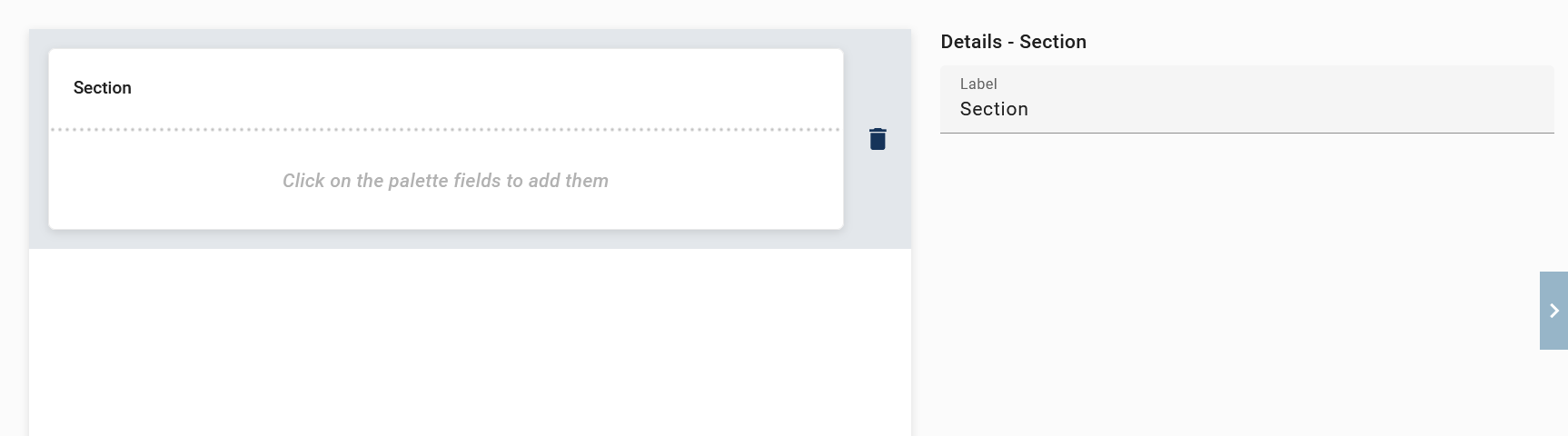
The section field can be used to create multiple sections with different column layouts. In the details in the right sidebar, you must enter an ID if the Repetitive option is selected. Otherwise, the ID is optional. Additionally you can select a label and the Mandatory, Read-only and Hidden attributes. Once you have assigned an ID to a section, it automatically becomes part of the IDs of all form fields contained therein. You can therefore only access the associated form fields using the combination of section ID and field ID. If a section is assigned the ID address and contains a form field with the ID street, it can be accessed via address.street.
Hint
Please note that if the Repetitive option is disabled, the previously entered ID remains saved in the background. To avoid saving errors caused by duplicate IDs, briefly re-enable the repetitions, delete the ID manually, and then disable the option again. In this context, also check and update all form fields within the section that reference this ID.
If the section is marked as Mandatory, all form fields within the section must be filled out by the user. If a section is marked as Read-only, the user cannot edit any form fields within that section. If the section is marked as Hidden, all form fields within the section will be hidden and will not be visible to the user.
As a ProcessApp Creator, you have the option to configure the visibility of your section during process execution. The visibility determines how the section is displayed. Navigate to the Expansion panel area in the right sidebar of the form editor. Using the corresponding drop-down menu, you can specify how the section is shown in the process. If you select Always visible (no panel), which is set as the default, the section will always be visible in the process and cannot be collapsed. With Expanded by default, the section is initially open but can be collapsed manually. If you choose Collapsed by default, the section is initially collapsed in the process and can be opened manually if needed.
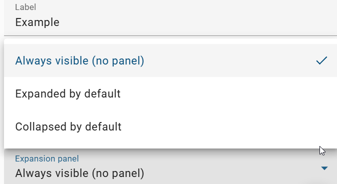
For sections configured as either Expanded by default or Collapsed by default, an arrow icon appears on the right side, allowing the section to be expanded or collapsed.

Note
Please note that a title is required for a collapsible section. It must be provided by the form creator.
To create a section with a specific column layout, open the form editor and add a new section from the left sidebar. Once a section has been added, you will receive a message informing you how to change its layout. Select the section to make further adjustments, such as adding form fields.
If you mark a section as Repetitive, you can set a minimum and maximum number. This determines how often this section can be displayed when filling out the form. You can enter fixed values or use values that change automatically, for example based on inputs in the form or earlier steps in the process. These values are calculated during execution and adjust automatically, so the correct number of sections is always displayed. In the process execution view, you will see the + [Section] button below the section as long as the maximum number has not been reached. You can also define whether the section title should be displayed in the repetitions.
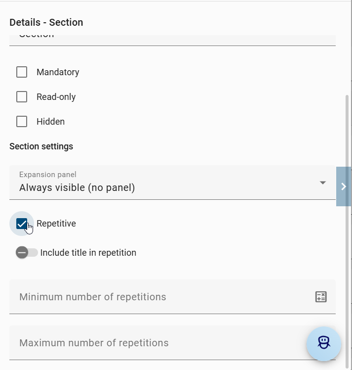
To link fields in a repetitive section to other fields within the same section, use the _index variable. This variable represents the current position of the respective entry in the repetition. The first entry always begins with the number 0.
Note
A section ID is automatically generated for each section and displayed in the upper right corner of the details. The section ID is available regardless of whether the Repetitive option is enabled or not. If the Repetitive option is enabled, the section ID is a mandatory field. Otherwise, it is optional. Even non repetitive sections thus have a unique ID that can be used for technical references or internal links.
Hint
Please note that the section ID refers to the entire section, while the _index refers to the specific entry within the section. Use the _index to ensure that you are referring to the correct line in the section.
Example:
You have these two form fields in the repetitive section:
postcode(text field)street(text field)
If you want the street field to appear in the form only when a postcode has already been entered and has exactly 5 characters, the condition must always refer to the entry that is currently being edited. This is especially important when several addresses are entered in a repeatable section. For this reason, the variable _index is used. It makes sure that only the fields in the same address row are checked. The condition checks whether the postcode field in the current entry contains a value and whether this value has 5 characters. Only then will the street field be shown for that specific address. By using the variable _index, each address is checked separately, so the street field always matches the correct postcode. Without the variable _index, it would not be clear which entry the condition refers to when multiple addresses are present.
When the form is processed, each element in the array is checked separately. The variable _index makes sure that the correct values are used for each element:
To access a specific street field within a repetitive section, replace the placeholder _index with the desired position number (starting at 0).
Example:
The expression postcodes[0].street returns the street name of the first entry.
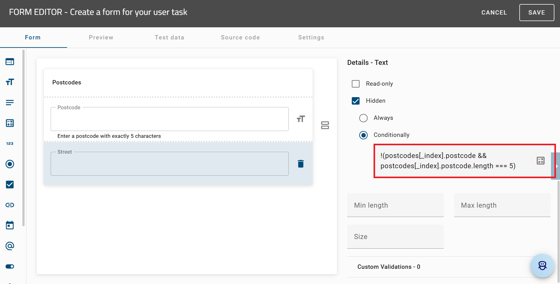
!(postcodes[_index].postcode && postcodes[_index].postcode.length === 5)
The condition checks whether a value has been entered in the postcode field and whether it has exactly five characters. If this is not the case, the street field remains hidden. As soon as a valid postcode with five characters is entered, the street field is displayed.
Note
Please note that the date picker icon will not appear if you add another section to the web form that contains a repetitive section with a date picker.
Once you have created sections and added form fields, you can click on the corresponding form fields to view an overview of their details in the right sidebar.
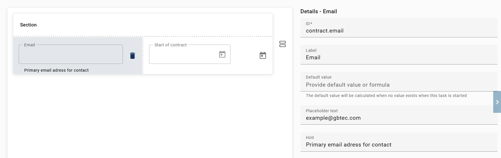
You can also add multiple rows to a section to efficiently enter and organize larger amounts of data. To do this, drag any form field (except the section field) above or below a row to add it to the section. The blue line will indicate the exact position.
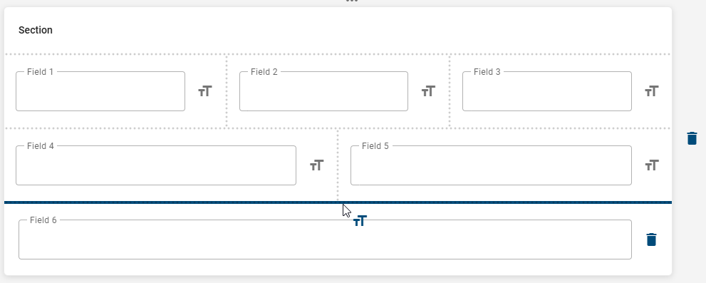
If you rearrange or remove fields within a section, the original column layout will be preserved. This means that the column arrangement remains unchanged, even if fields are modified. However, if you delete all fields from a row, the row will be removed.
It is possible to add multiple sections to the form, each with its own independent layout for the columns of form fields.
In the user role ProcessApp User, you can use the File field within repeatable sections of a form. This allows you to upload one or more input documents per repetition and reliably reuse these files in subsequent tasks. For more information, see here.
Note
Please note that for a section containing an error, the title of the affected section will be highlighted and displayed in red.
Note
Please note that any Section you create that has been assigned at least one ID or label will automatically be included in the list of process variables.
How can I view all process variables used in the form editor?
As a user with the ProcessApp Creator user role, you can view all process variables of the current diagram that are used in forms. To do this, you must be in GBTEC Process Design. If you are currently in GBTEC Work Orchestrator, you can switch to GBTEC Process Design by using the Process Design focus in the focus drop-down menu in the header. Open a diagram and check it out. Then click on an empty area of the canvas. Open the Details panel in the right sidebar. Select the Automation attribute group and mark the process as an executable process. Then switch to the Options panel and select Process Execution Editor. Click Open editor. The ProcessApp Configuration will then open and display all available process variables in a list.
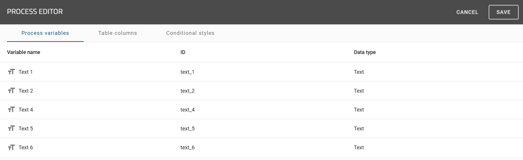
The Variable name is the label of a form field, the ID is the ID of the form field, and the Data type is the type of the form field. If you want to add more process variables, you need to configure additional form fields. For more information, see here.
You can also search for specific process variables. A search field is available for this purpose. You can use it to search for variables by name or ID. If needed, you can use the found variables for configuring custom columns in a ProcessApp. You can view already selected variables by clicking Only show selected variables.

Hint
Please note that process variables are only saved once in the list. This keeps the list clear and avoids duplicate entries. When a variable is created for the first time, it appears in the list. If the same variable is used again in other tasks, it will not be added again.
How can Arty help me with the configuration of a form?
As a user with the ProcessApp Creator user role, you can use our AI assistant Arty to help you configure a form. To do this, you must be in GBTEC Process Design. If you are currently in GBTEC Work Orchestrator, you can switch to GBTEC Process Design by using the Process Design focus in the focus drop-down menu in the header. Open a diagram and check it out. Then select an activity and set its task type to User in the Details panel on the right sidebar. After that, right-click the activity and open the form editor. For more information about creating and configuring a form, see here.
To use Arty, the AI-supported features must be enabled for you. In addition, a form must already exist or at least one form field must be added in the form editor. If these requirements are met, you will see the Arty button at the bottom right of the form editor.

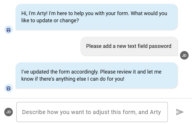
Click the button to open a chat with Arty. There, you can enter changes to the form and send them by pressing Enter or clicking the send button.
After you send your request, Arty updates the form and shows you the changes in the chat. You can then send further requests to Arty.
Warning
Please make sure that you provide Arty with all relevant information (e.g., position of the form field). Otherwise, Arty may not be able to process your request.
Tip
You can also link form fields automatically to existing process variables. Arty detects variables that already exist and can insert them into the form. You select the variables directly in the chat, so no manual assignment is needed. Existing variables are reused, and new variables can be created if required.
If you no longer need Arty’s help, you can close the chat using the X button. When you open the chat again, previous messages are no longer shown. Make sure to save your changes by clicking the Save button in the upper right corner of the form editor.
Tip
As a ProcessApp Creator, you can also use Arty to create a new form. Click the Generate form button to create a draft. The AI-supported features must be enabled for this. For more information, see here.
Hint
Please note that the AI-supported features of Arty are not included in the standard license. Please contact your representative for more information. Also refer to the notes on using the AI feature.
How can I test formulas in the form editor?
In the form editor, you can test formulas in all form fields in which a default value can be defined or the attributes Mandatory, Read-only or Hidden are available. To do this, select any form field in the form. In the Details panel in the right sidebar, next to the Provide default value or formula input field, you will find a button that enables extended input options and the testing of formulas.
For the attributes Mandatory, Read-only, and Hidden in the respective form fields, the option Conditionally must be selected to enable the button.
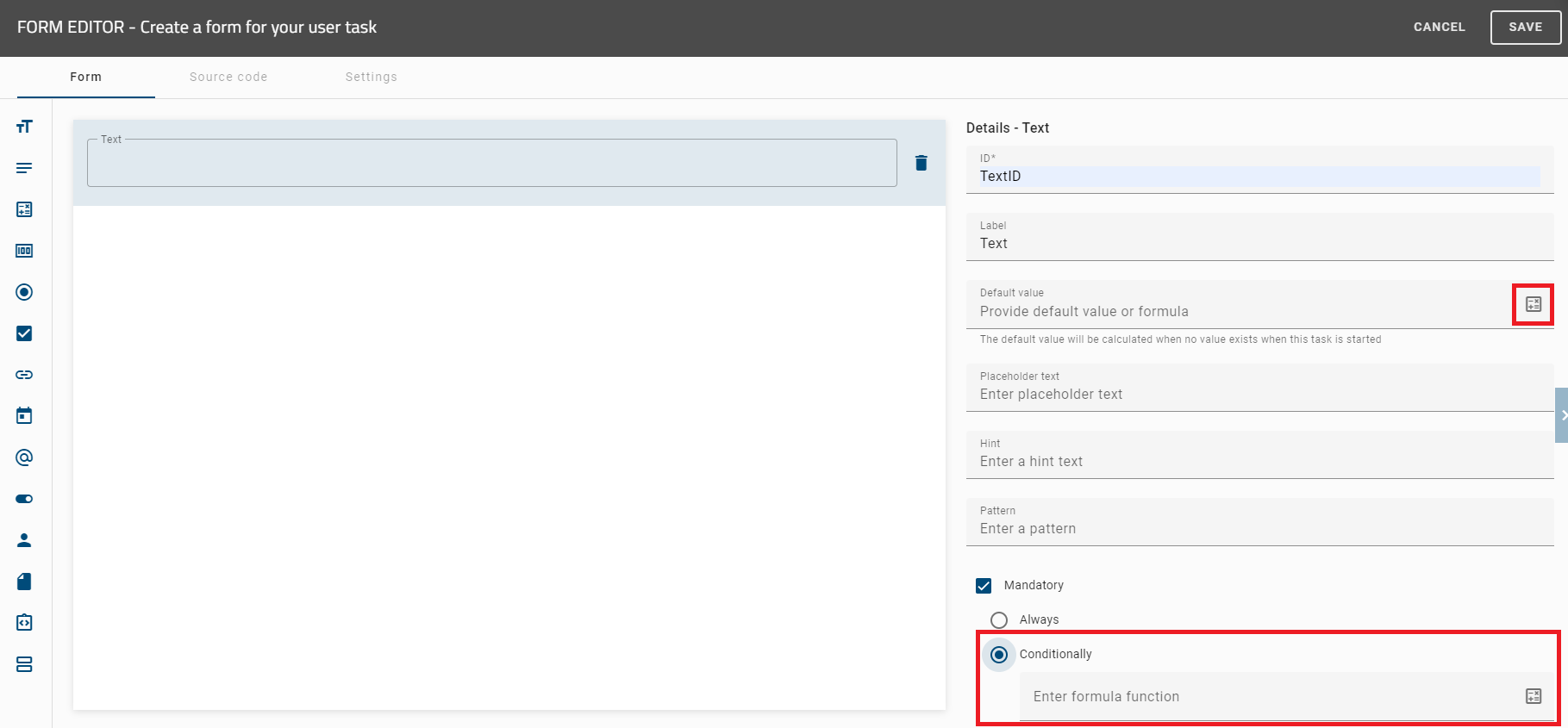
Once you have clicked on the button, a formula editor opens in which you can enter a formula to calculate the default value. To check your formula in advance in the form editor, you can enter variables in the Input variables input field and use the Evaluate button to test the formula. The result is displayed in the Output field as key-value pairs in JSON format.
You can then save your formula using the Save option. To discard your input, click the Close button.
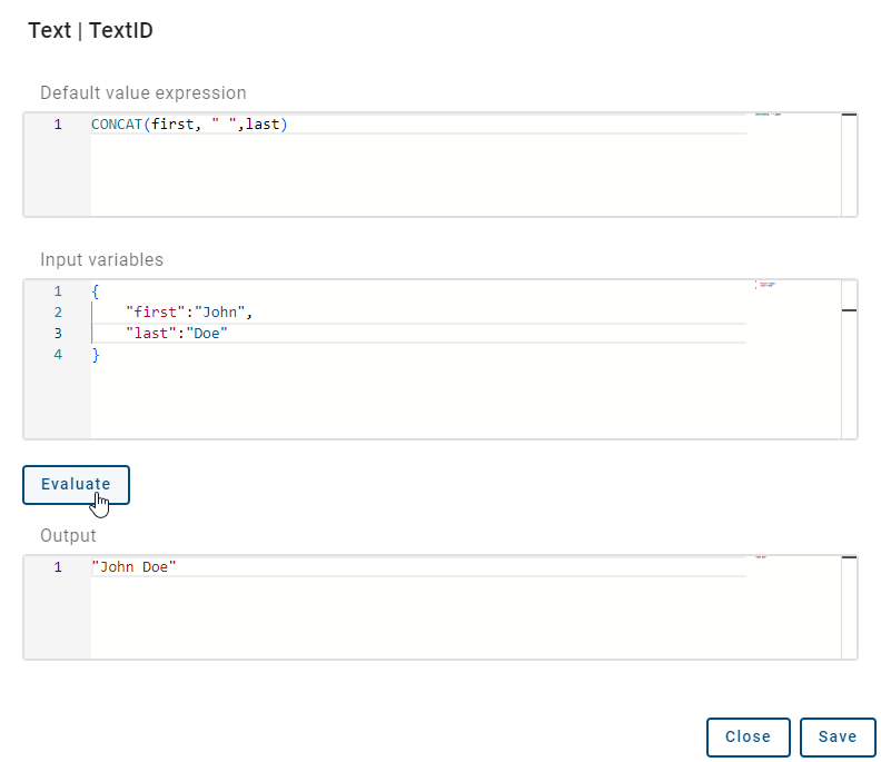
Code to copy and test:
Default value expression:
CONCAT(first, " ",last)

Input variables:
{
    "first":"John",
    "last":"Doe"
}
Hint
For more information about the formulas you can use, click here.
How can I preview the form in the form editor?
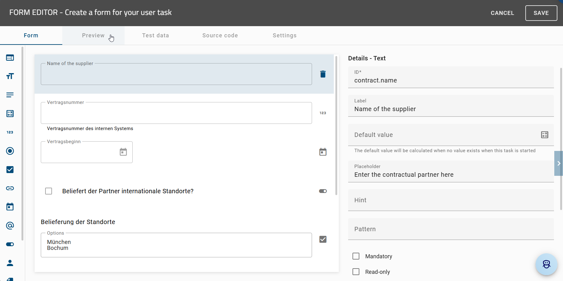
As a ProcessApp Creator, you can create a form for a task using the Form editor and check it at any time in a Preview. If you are currently in GBTEC Work Orchestrator, you can switch to GBTEC Process Design by using the Process Design focus in the focus drop-down menu in the header. Click on the Diagrams menu item in the left menu bar and open a diagram from the desired repository. After opening it, check out the diagram so that you can edit it. Then select an activity and set its task type to User in the Details panel in the right sidebar. You can then open the Form editor either from the context menu of the activity or via the Process Execution Editor in the Options panel.
After creating or editing a form, you can open a preview by clicking the Preview button. The preview is shown directly in your workspace and displays the current state of the form. It also includes unsaved changes so that you can review them immediately.
The preview shows the form as users will see it later in the process. You can interact with the form by entering values, selecting options, or clicking buttons. Required fields are highlighted and dependent fields are shown or hidden automatically.
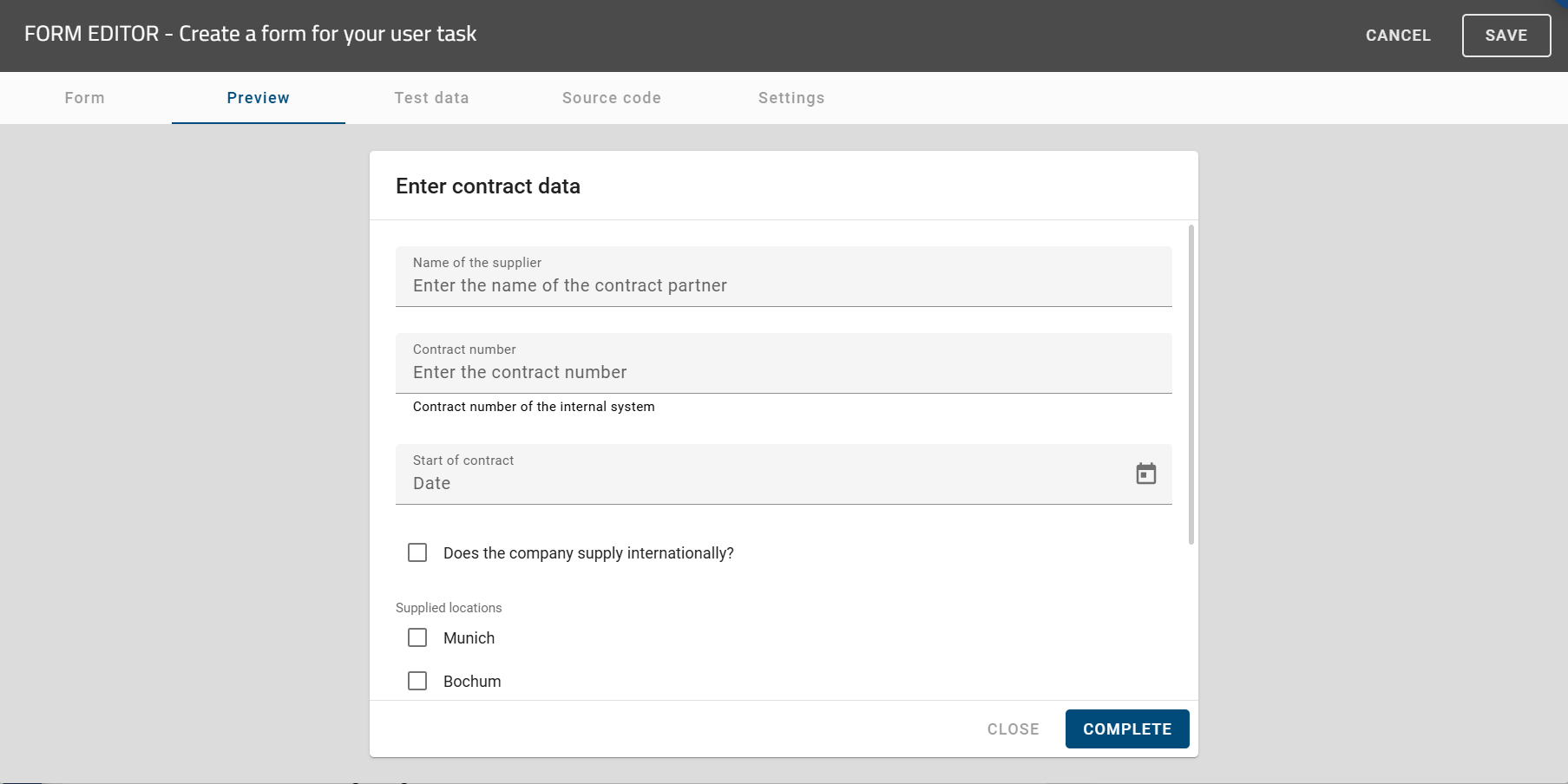
The form preview ensures that you can check the form in its current editing state at any time. This also includes unsaved changes, validations, and the display of the form fields. This makes the preview a reliable basis for further configuring and deploying the process.
Hint
Please note that an empty message is shown in the preview if no process variables have been added yet.
How can I use test data for my form in the form editor?
As a ProcessApp Creator, you can create a form for a task using the Form Editor and test it at any time with sample values. To do so, select Diagrams from the menu on the left in GBTEC Process Design and open a diagram from the desired repository. After opening the diagram, check it out so that it can be edited. Then select an activity in the diagram and set its task type to User in the Details panel on the right. You can then open the Form Editor either using the context menu of the selected activity or via the Process Execution Editor in the Options panel on the right.
In addition to the form preview, the Test data tab is available in the Form Editor. This area allows you to define sample values in JSON structure for the fields used in the form so that you can realistically test the form’s behavior without having to start the process itself.
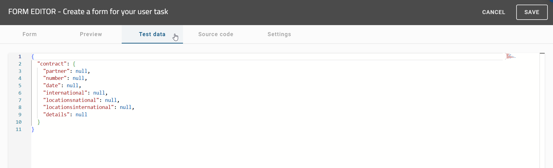
When you open the Test data tab, all fields used in the form are displayed automatically. For each field, you can enter suitable sample values, such as a name, a price, or a quantity. In addition, values are also prepared for fields that are not directly visible in the form but are used in the background, for example for calculations or placeholders.
As soon as you modify the Test data, the changes are applied automatically to the form Preview. The form updates immediately, allowing you to see the effects of your inputs right away. This makes it easy to verify whether calculations are displayed correctly, content appears as expected, and the form responds properly to different inputs.
The values entered in the Test data tab are retained and are not reset automatically. This allows you to further refine your form step by step and repeatedly test it using the same or adjusted sample values.
How can I rearrange the position of my elements within the form?
In the form editor, you can easily customize fields by dragging and dropping. You can drag and drop fields from the palette to a section, place fields from the base list anywhere in sections, and move fields from a section back to the basic list. You can also rearrange fields within a section. As you drag a field, a blue line always appears to mark the possible position, regardless of how far away the next field is.
Hint
Please note that it is not possible to insert a section into another section.
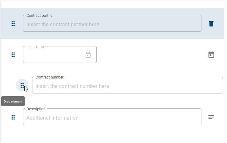
How can I remove one of my form fields from the form?
To remove a form field from the form you need to select the option Delete Element on the right side of the field. The entry will be removed from the list of form fields within the form.

How can I view and edit the source code of a form?
As a ProcessApp Creator, you can view the source code of the form and adapt it if necessary. This can be done manually by typing, copying, cutting or pasting something into the source code. To do this, open the form editor and select the Source code tab.
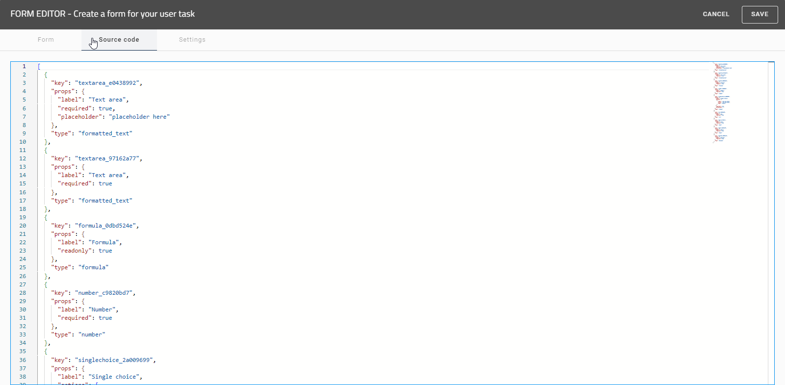
You can use various keyboard shortcuts within the source text to get a better overview:
1. Search and Navigation
Ctrl + F: Find in the current file.
Ctrl + H: Find and replace.
F3: Find the next match in the search.
Ctrl + F3: Select the next occurrence of the current word or selection.
Ctrl + G: Go to a specific line in the file.
Ctrl + Shift + O: Go to symbol in a file.
2. Text Selection
Ctrl + A: Select all text in the file.
Ctrl + L: Select the current line.
Ctrl + D: Select the next occurrence of the current word or selection.
Ctrl + Shift + L: Select all occurrences of the current word or selection.
Shift + ← / →: Select text left or right, character by character.
Ctrl + Shift + ← / →: Select text left or right, word by word.
Shift + ↑ / ↓: Select text line by line, up or down.
Ctrl + Shift + ↑ / ↓: Move the current line up or down while maintaining selection.
Ctrl + Shift + Home: Select from the current position to the start of the document.
Ctrl + Shift + End: Select from the current position to the end of the document.
Shift + Home: Select from the current position to the beginning of the line.
Shift + End: Select from the current position to the end of the line.
3. Text Editing
Ctrl + Z: Undo the last action.
Ctrl + Shift + Z: Redo the last undone action.
Ctrl + Shift + K: Delete the current line.
Ctrl + U: Undo the last cursor action.
Alt + Click: Insert a cursor at multiple locations (multi-cursor).
Alt + Shift + ↓ / ↑: Move the selected line down or up.
Ctrl + Alt + ↓ / ↑: Copy the selected line down or up.
Alt + ↓ / ↑: Move the selected line down or up.
4. Code Formatting
Alt + Shift + F: Format the code.
5. Code Folding
Ctrl + Shift + [: Collapse the current JSON block.
Ctrl + Shift + ]: Expand the current JSON block.
6. Line Insertion
Ctrl + Enter: Insert a new line below the current line.
Ctrl + Shift + Enter: Insert a new line above the current line.
Any changes you make in the source code are immediately updated and displayed in the form.
Hint
Please note that it is not possible to save or change the view if the source code is invalid. In this case you will be informed about the invalid source code within the source code.
How can I set validation rules in the form editor?
You can configure your forms to show validation and error messages when users enter incorrect data. This helps to improve data quality.
If you are currently in GBTEC Work Orchestrator, you can switch to GBTEC Process Design by using the Process Design focus in the focus drop-down menu in the header. In GBTEC Process Design, go to the Diagrams menu and open a diagram from the desired repository. After opening it, check out the diagram so that you can edit it. Select an activity in the diagram. Set the task type to User in the Details panel in the right sidebar. Then open the form editor either by right-clicking on the activity or by using the Process Execution Editor in the Options panel in the right sidebar.
Hint
Please note that you can only define validation rules if your process has been set up as an executable process.
You can now add a Custom Validation. To do this, first click on the desired form field. Then navigate to the Custom Validations section in the Form editor in the right sidebar and click on Add validation.
Warning
Please note that HTML fields, file fields, and section fields cannot be used when using validation rules.
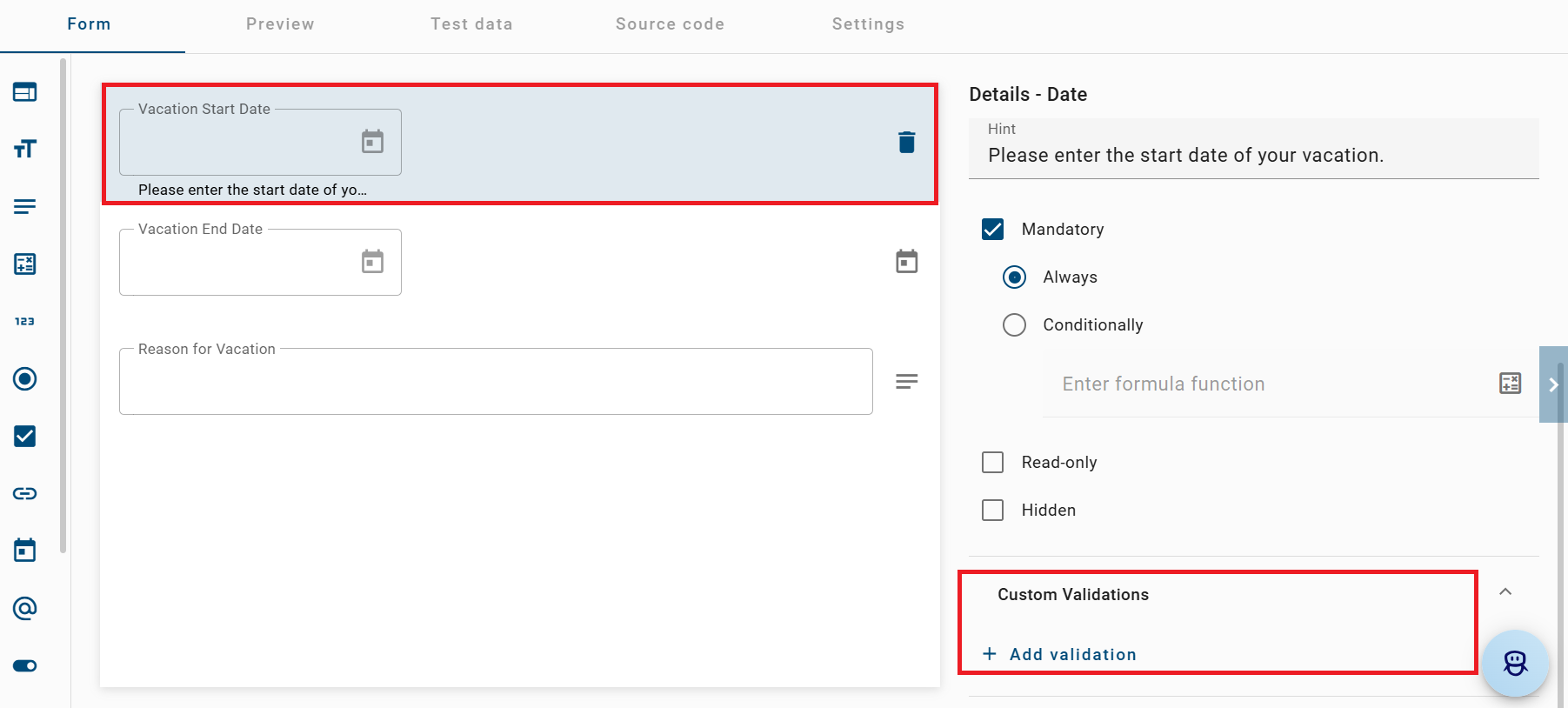
Next, define a validation that checks whether the users input meets the required criteria. Then specify an error message. This message is shown if the input violates the validation rule and explains what needs to be corrected.
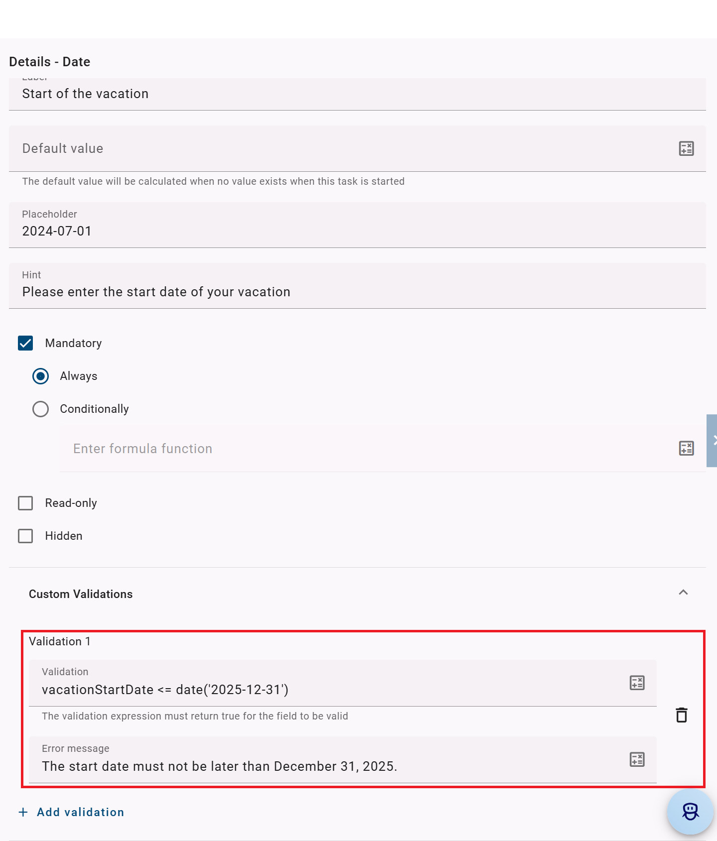
Hint
Please note that your custom validations must refer to the underlying ID of the corresponding form field.
Note
Please note that the validation formula is a logical expression. You must use comparison operators such as <, <=, >, >=, ==, or != to compare the user input with your defined criteria.
To save and apply your settings, click the Save button in the upper right corner of the form editor.
When you complete a task with custom validation and click the Complete button, the configured form is checked. This includes validation rules, unfilled mandatory fields, and pattern or format requirements. If the form contains invalid or incomplete entries, an error banner appears at the top of the process execution view. This banner shows all errors. The errors can come from your configured validations or from standard validation rules. The error banner gives a clear overview of all errors. Each error is easy to understand and clearly explains the problem.
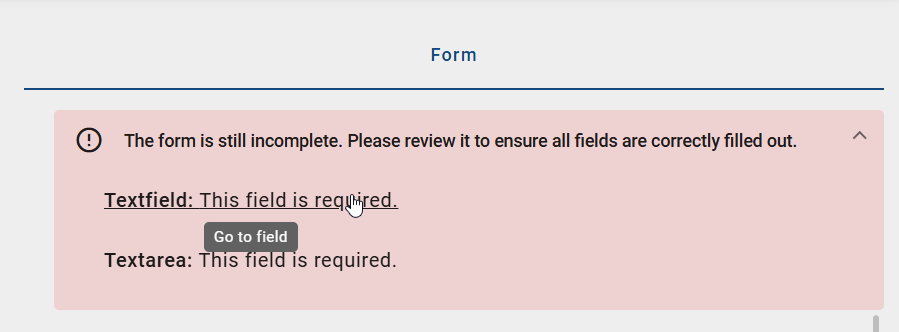
The errors listed in the error banner are interactive. When you click on an error, you are taken directly to the field where the error occurred. This makes sure that tasks can only be completed when all required inputs are correct.
Hint
You have the option of assigning any number of validation rules to each form field.
How can I create a signature task?
You can create your forms in a way that your users must authenticate themselves before they can complete the task. To create a signature task, the activity must be of the type User. Open the form editor of the corresponding activity and select the Settings tab.
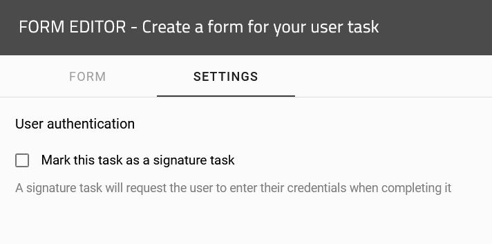
Here you have the option to select the Mark this task as a signature task checkbox. If you select this checkbox, your activity will be marked as a signature task and your users will have to authenticate themselves before completing the task. How the authentication process works can be found here.
Note
Please note that this function is not activated by default in your system and must be configured. To do so, please contact your contact partner at GBTEC.
How can I create a task for an external user?
As a user with the ProcessApp User user role, you can create and execute tasks for external users within a diagram. To do this, you must be in GBTEC Process Design. If you are currently in GBTEC Work Orchestrator, you can switch to GBTEC Process Design by using the Process Design focus in the focus drop-down menu in the header. Click on the Diagrams menu item in the left menu bar. You can either create a new diagram or check out an existing diagram.
While modeling, you can define a role by adding a pool. Then create two lanes to clearly separate internal and external processes. Place the start event, end event, and the internal activities in the internal lane. At least one activity must be placed in the external lane.
To define a lane as external and create tasks for external users, click on the lane you want to define as external. Then open the Details panel in the right sidebar. There, you will find the External option, which you need to activate by selecting the checkbox. Additionally, enter an ID of your choice in the Identifier attribute field.
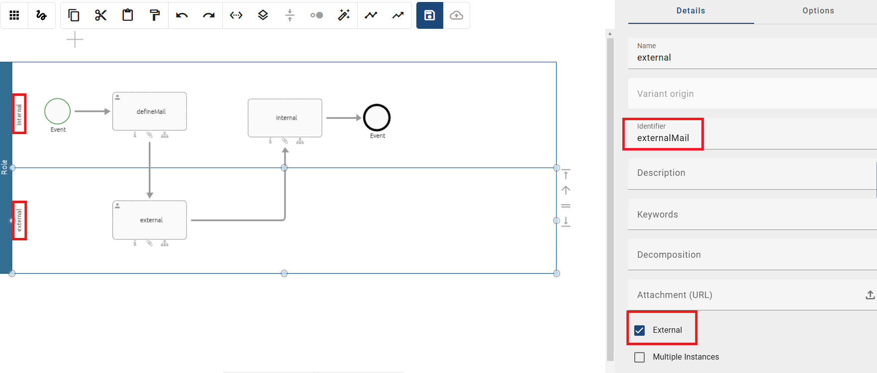
After marking the lane as external, assign the task type User to the activities in both lanes. Then open the Form Editor by right-clicking on the activity.
In the form editor, select the Text field from the left sidebar and add it to the form. In the right sidebar, enter the identifier from the external lane into the ID attribute. In this example, it is externalMail. Save and close the form editor. Repeat this step for both activities.
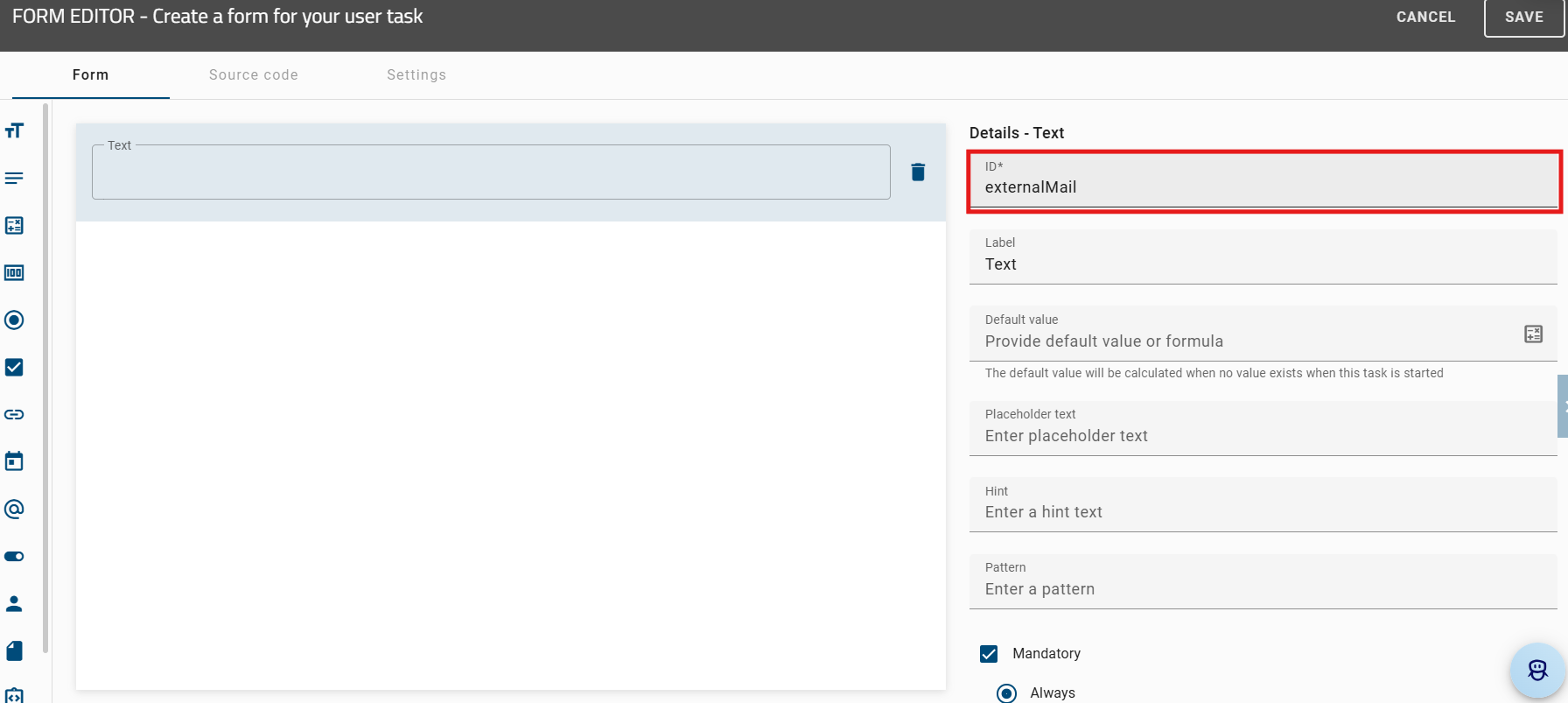
To send the task to an external user, enter the user’s email address. Then check in the diagram using the Check In button. After that, start a new process by clicking the Test ProcessApp button. When the process runs, you are taken to the process execution view. There, you can enter the external email address in the first task.

After entering the email address and completing the task, the external user receives an email with the task. For more information on how an external user can work on a task, see here.
Hint
You can also test external tasks. Please note that this is only possible in the Publish area.
Hint
Please note that the roles must be in the same pool. Otherwise, the activities cannot interact.
Hint
If you enter multiple email addresses, you must separate them with a semicolon.
Script task
How can I create a script task?
As a user with the ProcessApp Creator user role, you can execute tasks automatically in your process by using script tasks. The supported script languages are JavaScript and Groovy. From version 7.12.0, JavaScript uses the GraalVM Script Engine. The JavaScript ECMA version 5.1 is backward compatible and also supports features from version 13.0. You can find detailed information about the JavaScript ECMA standards used and the Groovy Engine in the following links.
Hint
The Nashorn JavaScript Engine is no longer supported from version 7.12.0.
Hint
The Groovy engine has been updated to version 4.0.12.
If you are currently in GBTEC Work Orchestrator, you can switch to GBTEC Process Design by using the Process Design focus in the focus drop-down menu in the header. In GBTEC Process Design, click on the Diagrams menu item in the left menu bar. You can either create a new diagram or check out an existing diagram. To use a script task, your diagram must be marked as executable process. Select an activity and set the activity type to Script.
To open the script editor, right-click on the activity and select Script Editor.
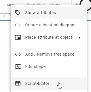
Alternatively, select the activity and open the Process Execution Editor in the Options panel. Then click Open editor.
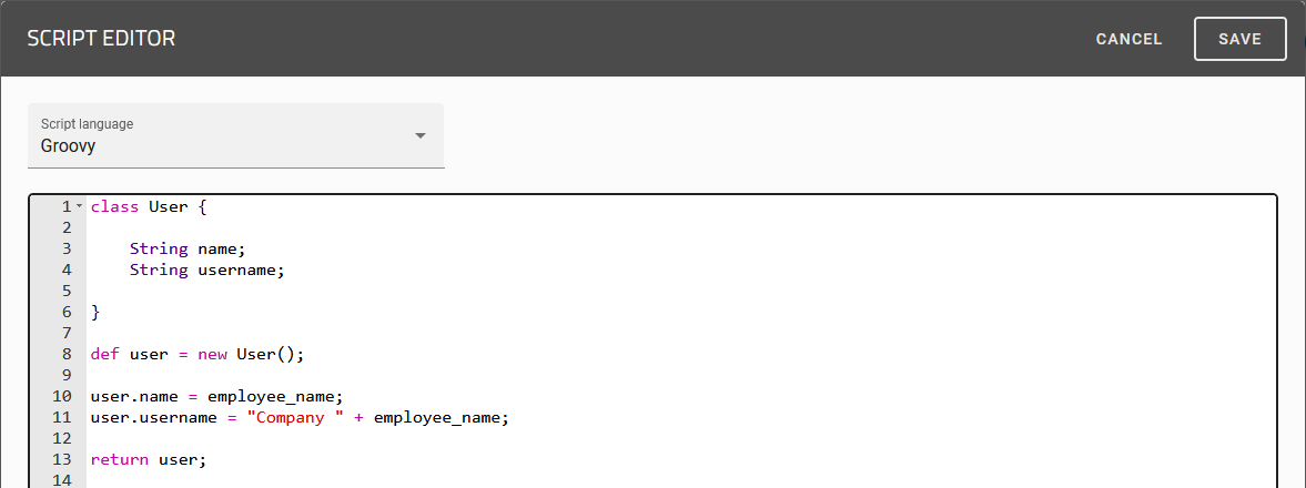
In the editor, select a script language from the drop-down menu and write your script. You can use process variables to adjust the script dynamically for each case. The example below shows a Groovy script. It uses the process variable employee_name and creates a new object called user. This object is then returned as a new process variable in line 13.
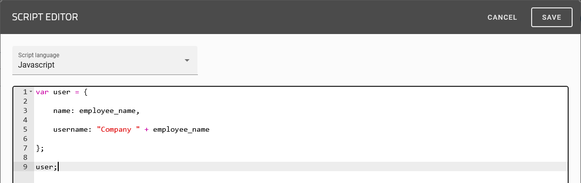
You can use process variables in JavaScript in the same way. The following example shows the same behavior. The last line of the script is returned automatically. In this example, the object user is returned as a process variable in line 9.
Warning
If the result is declared with var result = ..., you must return result again.
You can also test your script before completing the task. To do this, click on the Test your script button.
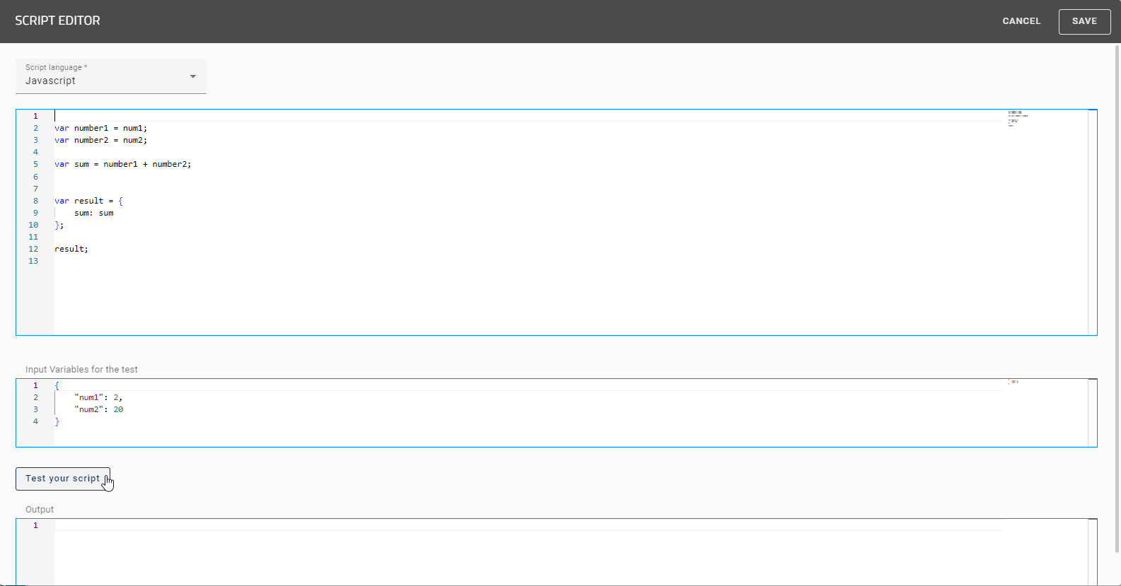
If the script runs successfully, the result is shown as key-value pairs in JSON format.
Note
Please note that outputs larger than 64 KB will not be displayed.
Afterwards, select Save in the top right corner to store your script and close the editor. If you click on the X icon located directly beside it, the editor will close without saving your changes.
You also have the option to use an ID, which is based on a User or a User Group, directly within the script editor. If you define an ID for a user or a user group in a previous activity of the type User, you can reference this ID in a later activity of the type Script. When you use the ID without specifying a particular attribute, the returned value depends on the type of the identity. For identities of type USER, the user’s email address is returned automatically. For identities of type USER_GROUP, the name of the user group is returned instead.
In addition, you can access specific attributes of the identity:
.id– returns the ID of the identity.language– returns the currently selected content language of the user or the users within the group.name– returns the name of the user or the user group.email– returns the email address of the user (not available for groups).type– returns the type of the identity (USER or USER_GROUP)
These attributes are available within the script editor and can be used for further processing as needed.
Afterwards, select Save in the top right corner to store your script. If you click on the X icon located directly beside it, the editor will close without saving your changes.
Hint
Please use the correct JavaScript syntax to add a list from a script task to the process variables. This is demonstrated in the following.
*JavaScript*
var userList = ["John Doe", "Max Mustermann"];
vars = {
    scriptListVar:userList
}
If you use the syntax above, each entry in the list will be stored as a separate process variable (here of type string). To store the entire list as one variable of type list, use one of the following alternatives.
*JavaScript*
var List = Java.type("java.util.List");
var userList = List.of("John Doe", "Max Mustermann");

vars = {
    scriptListVar:userList
}
*JavaScript*
var Arrays = Java.type("java.util.Arrays");
var userList = ["John Doe", "Max Mustermann"];

vars = {
    scriptListVar:Arrays.asList(userList)
}
You can also use date values as output variables in the script. Date values in process variables are stored as String. However, there is one exception for JavaScript. If a Date object is returned directly, the variable may contain the value null. To avoid this, the date should be converted to a string. The following examples show the different behavior of the two scripting languages.
Hint
Please note that scripts cannot return date values of the data type Date.
Warning
Please note that tasks that are active during a system restart are set to error status. This applies to both script and service tasks. These tasks are assigned to the responsible users and trigger an email notification. You can restart these tasks after the system is available again.
Using Javascript:
let localdate = new Date()
output = {
    javaScriptDate: localdate,
    javaScriptDate_String: localdate.toISOString()
};
If you want to return the javaScriptDate object directly, the result will be null. To return the date correctly, convert it to a string using methods such as toISOString() or toJSON(), as shown in javaScriptDate_String.
Using Groovy:
Map output = new HashMap();
Date testDate = new Date();
output.put("groovyDate", testDate);
return output;
Returning a Map with a Date object always returns the date as a string, unlike in JavaScript.
How can I create code snippets using AI in the Script-Editor?
As a user with the ProcessApp Creator user role, you can use Arty to generate code in the script editor. If you are currently in GBTEC Work Orchestrator, you can switch to GBTEC Process Design by using the Process Design focus in the focus drop-down menu in the header.
In GBTEC Process Design, navigate to the Diagrams menu item in the left menu bar and open the corresponding diagram. To open the script editor, the corresponding diagram must be marked as an executable process. The task type of the activity must be set to Script.
You will then find the Script Editor option in the context menu for the activity, which you can access by right-clicking on the activity.
Alternatively, you can open the script editor by selecting the activity and navigating to the Process Execution Editor option in the Options panel in the right sidebar. There, you will find the Open editor button, which allows you to open the Script Editor.
To generate code snippets in JavaScript or Groovy using AI, click the Arty icon at the lower right of the script editor.
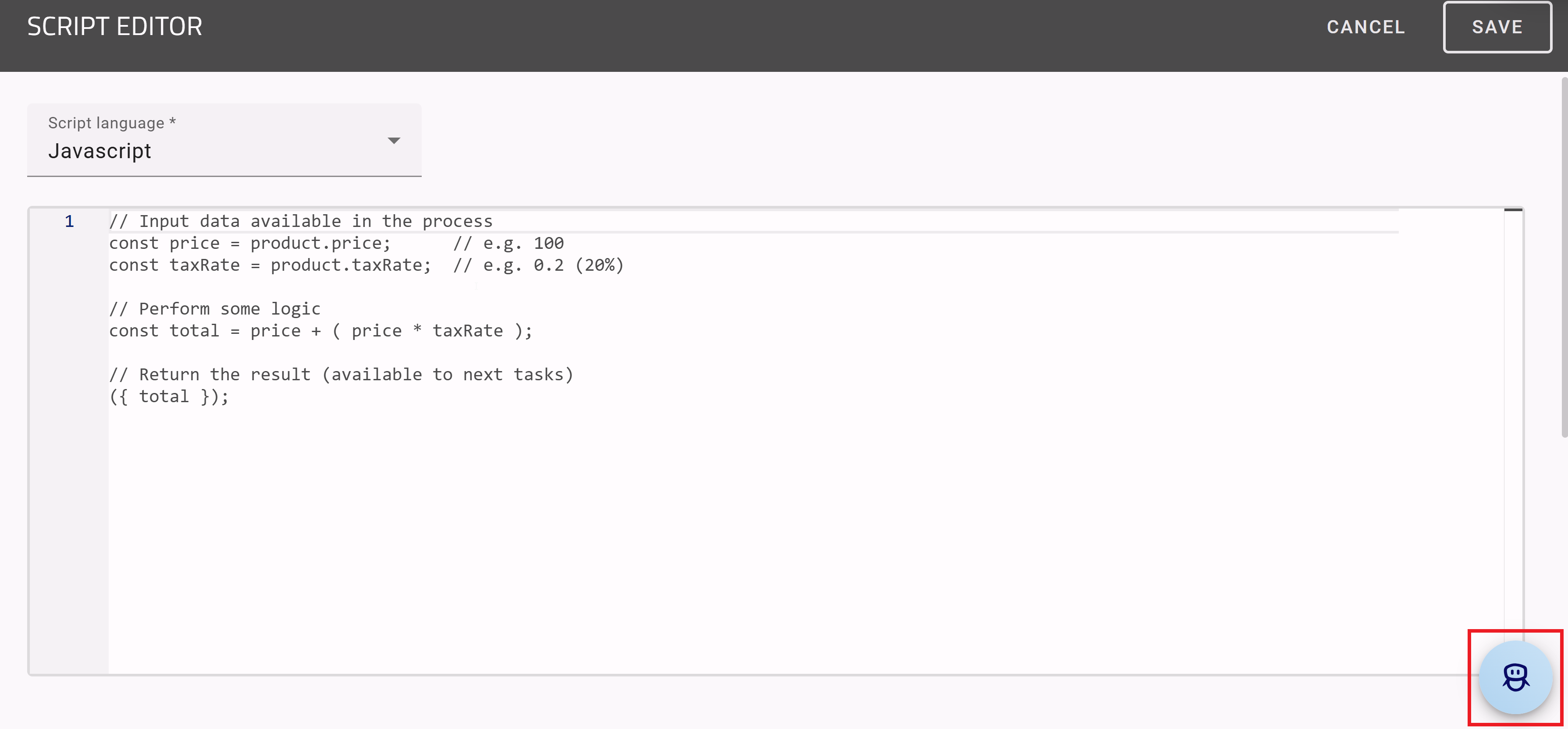
Hint
Please note that a separate license is required to use this feature. Please also refer to the Notes on using the AI feature.
In the chat that opens, enter a description of what you want to create or change. The generated code will be inserted directly into the script editor.
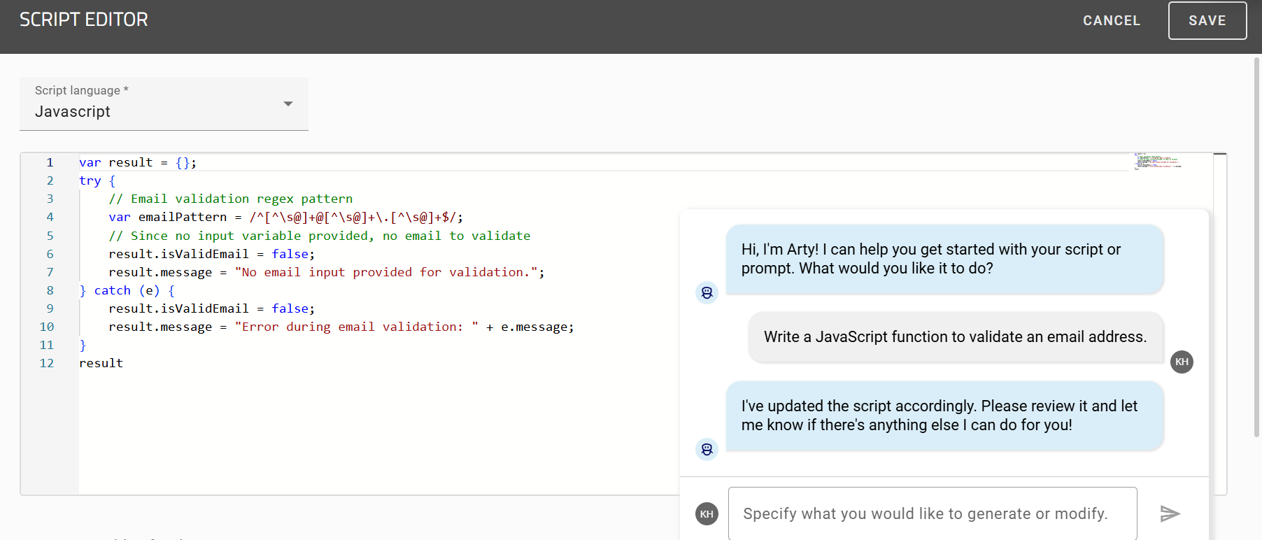
Further examples of input requests to Arty could look like this:
Generate a Groovy function that increases the process variable order number by one.
Update the code to also create a console message.
Create an appropriate AI prompt for this task.
Hint
Please note that your instructions to Arty should be as precise as possible. Otherwise, Arty may not understand your request and will ask you to rephrase it.
How can I create a script task with the help of AI?
As a ProcessApp Creator, you can create a script task with the help of our AI assistant Arty. To do so, open the script editor in the corresponding diagram in GBTEC Process Design. The corresponding diagram must be marked as executable process and the task type of the activity must be of type Script.
Afterwards, right-click on the activity to open the context menu and select the entry Script-Editor.
Alternatively, you can open the editor by selecting the activity and choosing Process Execution Editor in the Options panel. There you will find the button Open editor. Select it and the script editor will be opened.
In the Script language field, select AI Prompt from the drop-down menu. Then, enter a prompt for Arty in the upper input field and specify the relevant variables in the Input Variables for the test field. To preview the result before completing the script task, click Run test.
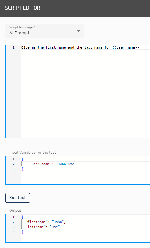
The placeholders in the upper input field will then be replaced with the specified input variables and the defined prompt will be executed as Output. If the script runs successfully, you will receive the output as key-value pairs in JSON format.
When entering a variable as a placeholder, you can choose between JUEL expression and String replacement. You specify the desired variant directly in the drop-down menu in the upper area of the Process Execution Editor in the Options panel in the right sidebar.
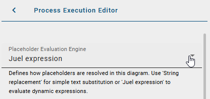
Please note that both variants are not supported at the same time. Diagrams that were created before the 8.0.0 version automatically use the previous string replacement logic. For newly created diagrams, however, the JUEL variant is now preselected by default. You can adjust the selected option at any time, but switching new diagrams to String replacement is not recommended.
Tip
You can find more information about JUEL expressions here.
Hint
Please note that the AI-enabled feature of Arty is not included in the standard license. Please contact your representative for more information. Please also refer to the notes on using the AI feature.
How can I retrieve data from a data table using SDK functions in a script task?
As a user with the user role ProcessApp Creator, you can use data from an uploaded data table in a process. You can retrieve the data with an SDK function in a script task and use it for further processing.
The scripting languages JavaScript and Groovy are supported. From version 7.12.0 and later, JavaScript is based on the GraalVM Script Engine. JavaScript ECMA version 5.1 is still supported and can also be used with the features of ECMA version 13.0. For more information about the supported JavaScript standards and the Groovy Engine, see the following links:
If you are currently in GBTEC Work Orchestrator, you can switch to GBTEC Process Design by selecting the Process Design focus in the focus drop-down menu in the header. Open the Diagrams menu item in the left menu bar. You can either create a new diagram or check out an existing diagram. To open the script editor, the corresponding diagram must be marked as an executable process. The task type of the activity must be Script. You can then open the Script-Editor from the context menu of the activity by right-clicking the activity.
Create a script task to access a data table. In the Script language field, select the language you want to use from the drop-down menu.
To retrieve data from a data table, use the command dataTables.get("<table_name>").query().list(). Before you can retrieve the data, the data table must exist in GBTEC Work Orchestrator.
To create a data table, switch to GBTEC Work Orchestrator by selecting Work Orchestrator in the focus drop-down menu in the header. Open the Administration menu item in the left menu bar and select the Data Storage tile. There you can create a data table and upload an Excel file as the data source.
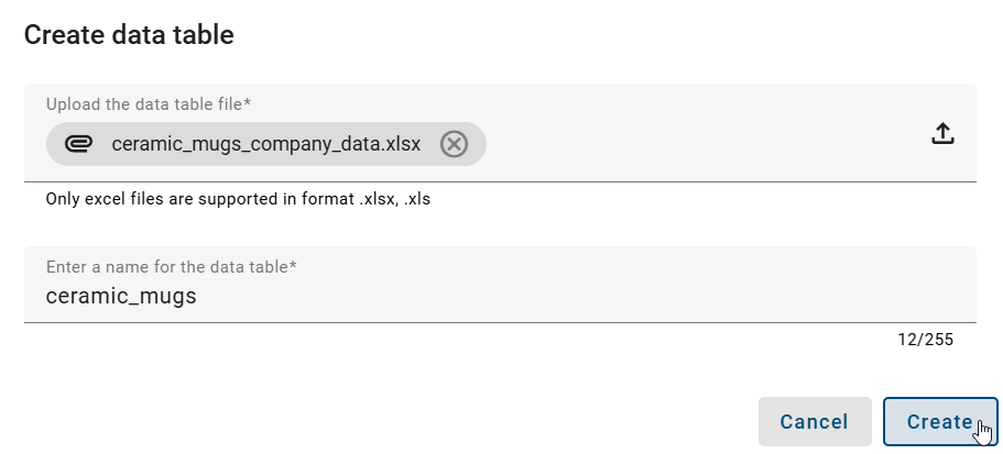
The data table must have the same name that you use in the Script Editor. In our example, the data table is called ceramic_mugs. You can access this data table in the script task with the command dataTables.get('ceramic_mugs'). Make sure that the name in the script task matches the name of the data table exactly.
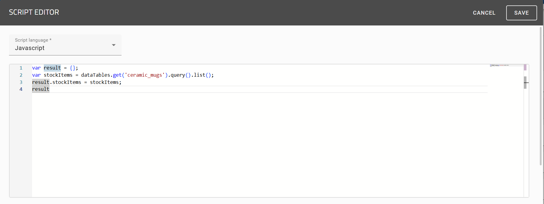
Tip
Pay special attention to the spelling of the data table name. Even small differences or typos can prevent the data table from being found.
If you do not want to retrieve all columns of a data table, you can use the command .columns() to select the columns that should be returned. This means that only the values you need are loaded.
The following example returns only the columns age and name from the data table persons:
dataTables.get("persons").query().columns("age", "name").list()
The result contains only the selected columns:
[
  { "age": 30, "name": "Anna" },
  { "age": 22, "name": "John" },
  { "age": 20, "name": "Ben" },
  { "age": 20, "name": "Mia" }
]
If you use .columns() multiple times in one query, only the last call is used.
dataTables.get("persons").query()
   .columns("age", "name")
   .columns("age", "name", "gender")
   .columns("age")
   .list()
In this example, only the column age is returned.
Note
Column names are not case-sensitive.
You can restrict the returned rows by using the .filter() function. You add this function to a query that you have previously created in the code. This way, only the rows that meet a specific condition are loaded.
The following example returns only the rows where the value of the age column is greater than 21:
dataTables.get("persons").query().filter("age > 21").list()
The result contains only the matching rows:
[
  { "age": 30, "name": "Anna" },
  { "age": 22, "name": "John" }
]
Filters can be used for numeric values, strings, and boolean values (true/false). If you compare a text value, for example a name, it must be enclosed in quotation marks.
dataTables.get("persons").query().filter("name == 'Anna'").list()
dataTables.get("persons").query().filter("active == true").list()
If no entry in your table meets the filter condition, the function returns an empty list.
dataTables.get("persons").query().filter("age == 99").list()
If the filter expression contains an unknown column or is invalid, an error message is returned.
The commands .size() and .getColumnDefinitions() support you when working with data tables. Use .size() to determine the number of entries. Use .getColumnDefinitions() to get information about the table structure, such as column names and data types.
Switch back to GBTEC Process Design by selecting the Process Design focus in the focus drop-down menu in the header. In the Script Editor, use the SDK function to retrieve the desired data table. When you click the Run test button, you receive a structured output. This output contains the data from the table, such as column names, row values, and individual fields.

For example, if the data table ceramic_mugs contains entries such as ProductID and Name, you can access these values and use them in your process.
Note
Please note that a data table must contain at least one entry. Otherwise, there is no data that can be processed further.
E-Mail
How can I create an email template?
You can integrate send tasks in your process to enable users to send emails based on a template. In order to change the email template, your diagram has to be marked as an executable process in the attributes. The activity type of the task has to be Send.
Afterwards, right-click on the activity to open the context menu and select the entry Email template editor.
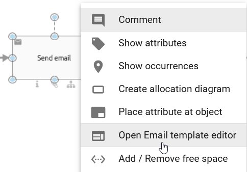
Alternatively, you can open the email template editor via the Process Execution Editor in the Options of the activity.
In the upper fields, you can enter the recipient in To, the email addresses in Reply to, Cc and Bcc, as well as a subject. The template can be written in the text field below. There you can find various formatting functions in the header.
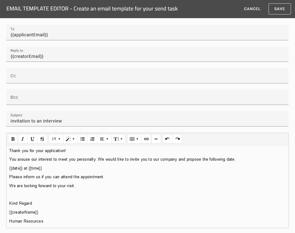
The To function also allows you to specify user groups. The email will then be sent to all members of the specified user group.

Note
Please note that when specifying multiple recipients in a send task, the individual email addresses must be separated by a semicolon. For example, enter the recipients in the following format {{email1}}; {{email2}}. It is also possible to use an e-mail address together with a group name, for example {{email1}}; group name. Only in this way will all recipients be taken into account correctly.
Note
Please note that you should not use curly braces ({{}}) with user groups.
By using the Reply to function, you can specify exactly one email address to which all responses to your sent email should be forwarded.

Note
Please note that the Reply to field is only taken into account if the Send email automatically option is activated. However, if more than one email is specified in the Reply to field and the email is sent automatically, the status of the send task will change from In progress to Error. For manually sent emails, the Reply to field is ignored.
Process variables can be used in every field in the editor and result in a dynamic template that is automatically adjusted in GBTEC Work Orchestrator. The variables are replaced with the case-specific values in the form of each case as soon as they are set in prior process steps. Integrate process variables via double curly braces: {{VariableName}}.
When entering a variable as a placeholder, you can choose between JUEL expression and String replacement. You specify the desired variant directly in the drop-down menu in the upper area of the Process Execution Editor in the Options panel in the right sidebar.
Please note that both variants are not supported at the same time. Diagrams that were created before the 8.0.0 version automatically use the previous string replacement logic. For newly created diagrams, however, the JUEL variant is now preselected by default. You can adjust the selected option at any time, but switching new diagrams to String replacement is not recommended.
Tip
You can find more information about JUEL expressions here.
Note
Please note that you can include process variables with html formatted values in the text editor. For such values, you must add a ” -html” (attention: with a blank space!) to the process variable name. Otherwise the formatting will not be processed. Consider a process variable {{CompanyName}} for which the values are given with a formatting (for example, in bold over “<b>GBTEC Software AG</b>”). If you use the placeholder with the html tag {{CompanyName -html}} in the text editor of your template, the value will appear with the defined formatting (in bold in the example).
How can I use process variables in an email template?
As a user with the ProcessApp Creator user role, you can use process variables directly in an email template. If you are currently in GBTEC Work Orchestrator, you can switch to GBTEC Process Design by using the Process Design focus in the focus drop-down menu in the header. Then go to the Diagrams menu item in the left menu bar. There, you can either create a new diagram or check out an existing diagram.
To use an email template in GBTEC Process Design, the corresponding diagram must be marked as an executable process. The activity type of the activity must be set to Send. Open the diagram. Select an activity and open the Process Execution Editor in the right sidebar in the Options panel. Alternatively, you can right-click the desired activity and select the Email template editor option from the context menu. Then, use the Process variables button to select the required process variables.
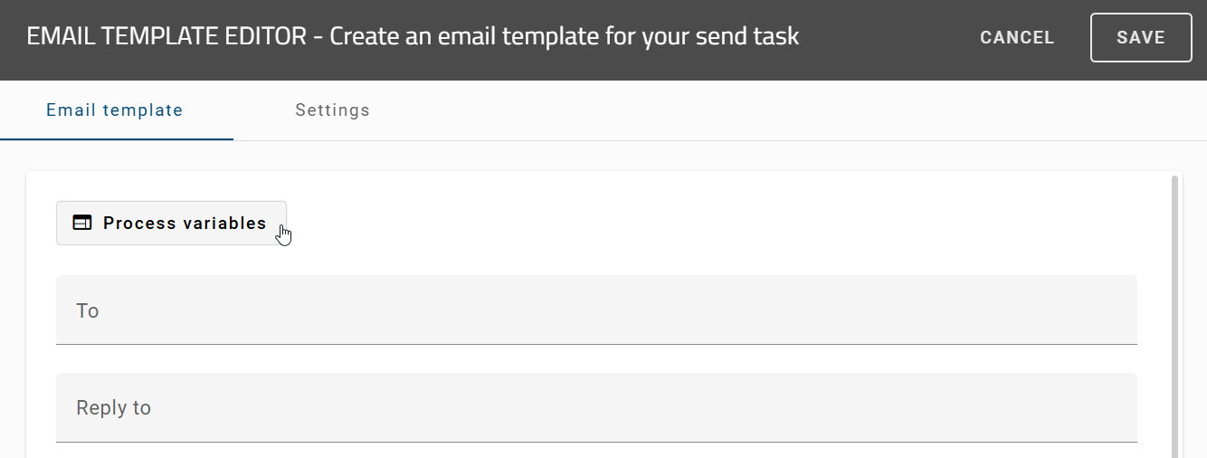
In this menu, you can see all variables used in the process. The variables are shown in alphabetical order. If no variables are defined, none will be displayed. You can use the search field to find a specific process variable.
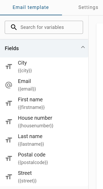
You can use the process variables directly in your email template. To do so, drag and drop the corresponding variable into the desired field of the email template.
Hint
Please note that to use the drag and drop function, you must place the mouse on the button to the right of the process variable.
When the email is sent, the process variable is automatically replaced with its current value. The email template itself does not change.
Hint
Please note that if no value is defined for a process variable, the corresponding part of the email remains empty.
How can I send an email automatically?
As a ProcessApp Creator you have the possibility to configure your emails to be sent automatically. To do this, open the Settings tab in the Email template editor and activate the option Send email automatically. When you start this task in GBTEC Work Orchestrator, your mail will automatically be sent from a no reply address. If you use process variables in your form, they will be automatically replaced with their corresponding value.

If the automatically sent email is supposed to contain an attachment, the desired file can already be included to the case in GBTEC Work Orchestrator. Model a preceding activity connected to an output object which is either a document, business object, norm or data store. Add the same object as input to the send activity. Then, the responsible of the corresponding task can upload a file in the form and complete the task. When the send task is started, the file is automatically attached.
Note
Please note that the input is only attached if the email is sent automatically (option Send email automatically activated).
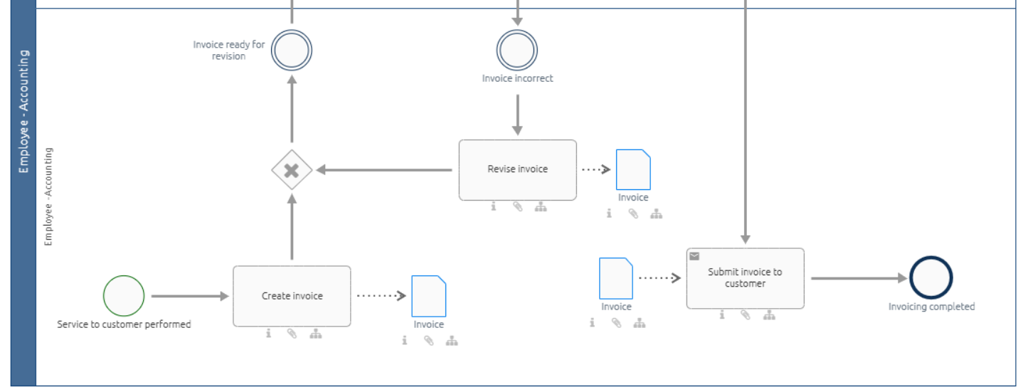
In the example above, the document “Invoice” is the output of the task “Create invoice” and the input of the send task “Submit invoice to customer”. The attachment of the email will be the latest version of the file in case. Thus, if the responsible uploads a new file (version) when working on the task “Revise invoice”, this file is attached to the email.
If your process variables are empty or not existing, GBTEC Work Orchestrator will display an error message and you have to send the mail manually via a human task. Alternatively, you got the option to replace these kinds of process variables with empty strings. For that you need to select the option Replace placeholders with empty values if process variables are missing.

Tip
Use the form editor to enable users to define the process variables in prior steps.
Warning
If an email is sent manually, there is a restriction for the length of the template. If your template is longer than a certain length, GBTEC Work Orchestrator will automatically truncate the mail and only a part of it will be displayed in your email client. If the email is sent automatically, this restriction does not hold.
How can I set up an email test configuration?
As a ProcessApp Creator, you have the ability to configure an email test setup. To do this, open the Settings tab in the email template editor. In the Email Test Configuration section, you will find two options available.
Send to defined recipient in Studio environment: If you activate this option and publish the process, emails in the Studio environment (development environment) will be sent to the recipients defined in the process. The subject line of each email will automatically include the prefix [Test mail].
Send to defined recipient in Test environment: If you activate this option and publish the process, emails in the Test environment will be sent to the recipients defined in the process. The subject line of each email will automatically include the prefix [Test mail].
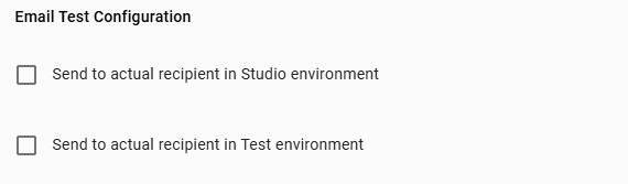
If you activate both options, emails will be sent to the recipients defined in the process in both the Studio environment and the Test environment. In this case as well, the subject line will automatically include the prefix [Test mail].
In addition, you have the option to specify alternative email addresses for testing purposes. These can be entered in the Enter alternative email addresses for testing field. If alternative test addresses are provided and sending to actual recipients is disabled, emails will be sent exclusively to these test addresses.
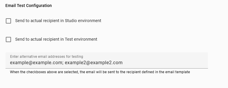
Warning
Please note that the alternative test email addresses are only considered as long as the options Send to defined recipient in Studio environment and Send to defined recipient in Test environment are not activated. Once one of these options is enabled, the alternative test addresses are ignored and emails are sent exclusively to the recipients defined in the process.
Note
Please note that multiple alternative test email addresses must be separated by a semicolon or a comma.
Hint
Please note that currently no user groups can be used as alternative test email addresses.
Service Task
With a service task, you automate recurring steps in your process without writing any code. The configuration dialog of the service task offers you four options:
REST: Exchange data with external systems, for example to retrieve information from another application or send information to it.
Reports: Automatically create an output document instead of assembling it manually.
Image Recognition: Extract data from an uploaded image, for example an invoice, without entering it manually.
MCP Server: Call a tool from an MCP server without configuring your own REST call.
The following sections explain how to set an activity as a service task and open the configuration dialog.
REST
GBTEC Work Orchestrator offers you the possibility, in interaction with your GBTEC Process Design, to exchange data via REST endpoints. The REST calls are defined in your GBTEC Process Design and automatically executed via the processes in GBTEC Work Orchestrator. The data which is resulting from these REST calls is then stored in process variables and can be used and displayed for further tasks during the process flow of the case.
Note
You have the possibility to define your REST request in the REST configurator described further on. This request is executed prioritized. If you have defined a REST call in a previous version via the Service call attributes and did not set any configuration in the REST configurator, the Service call attributes will be used as fallback.
How can I define my REST calls?
As a user with the ProcessApp Creator user role, you can configure a REST call in GBTEC Process Design. If you are currently in GBTEC Work Orchestrator, switch to GBTEC Process Design by using the Process Design focus in the focus drop-down menu in the header. Click on the Diagrams menu item in the left menu bar. You can either create a new diagram or check out an existing diagram. Open a diagram. Mark the diagram as an executable process and set the activity type of the activity to Service.
Afterwards, right-click the activity to open the context menu and select the option Service configuration.
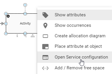
Alternatively, you can open the editor in another way. First, select the activity in your diagram. Then go to Options and open the Process Execution Editor. There you will find the button Open editor. Click it to open the Service configuration.
A dialog opens where you can define your REST call. Click on the REST option.
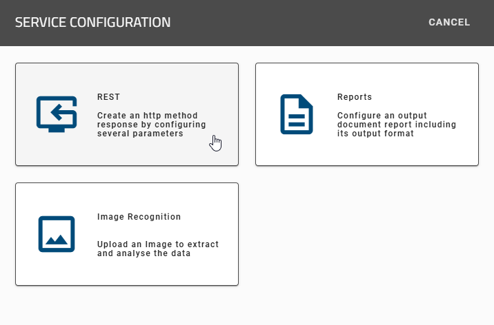
You will go through three steps. In each step, you can click the fields to edit them or choose an option.
Tip
You can also define your REST calls dynamically via process variables. For example, the header data or request body can depend on the data of each case.
1. Connection
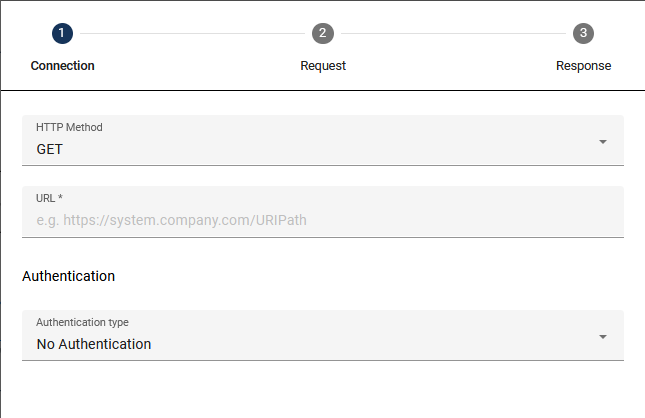
HTTP Method: In this field, select the HTTP method which you want to use for your call. The supported HTTP methods are listed below. If no method is specified, the default value for this field is GET.
DELETE
GET
HEAD
PATCH
POST
PUT
OPTIONS
TRACE
URL: Enter the URL path of your REST endpoint here (e.g.: http://serviceUrl:port/service/1).
Authentication: Here you can select the type of authentication that you want to use for your REST Call. We offer you different options for authentication:
No Authentication: You do not need any authentication and therefore do not need to enter more details.
Basic Authentication: When you select this option, two new input fields will appear where you can enter your username and password for the desired service.
OAuth2: Three new input fields will appear when you select this option. You need to enter the Client ID, the Client secret and the Authentication URL. Via the eye icon you can hide and show the Client secret.
API Key: After selecting this option, two input fields will appear: Key and Value where you can enter your API key and its value. Below the fields you have the option to add the key-value pair to your header or to your query parameters.
Go to the second step using the button NEXT. Alternatively, you can click the tabs Connection, Request and Response to switch between the steps arbitrarily.
2. Request
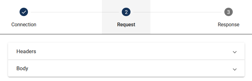
The input fields expand depending on the selected option.
Request header: Here you can enter all header data that has to be transferred in the REST call. This data is in a key-value table. Click on the plus-sign to add new entries or select the recycle bin icon to delete an entry.
Body: Here you can enter the content that has to be transferred in the REST call. In the drop-down menu Type, choose one of the following options:
JSON: Here you can enter the content in the Request body field using JSON-structure.
Binary (file): Choose this type to read the request body from a file. In this case, the request body will contain only the contents of the file.
Multipart (file): This type displays a key-value table where the request body is partially generated from a file. Once you have entered a key, you can choose between Text and File under “Type”. If you select Text, you can enter text including variables as placeholders. If you choose File, you can specify an identifier for a file. You can also enter multiple files in the table by clicking Add new empty row and creating a combination of Text and File.
If you choose one of the types that import the content from a file, another field appears where you can link the desired file. Use the process variable from the identifier attribute of the file. You can find a detailed explanation in the linked section.
When entering a variable as a placeholder, you can choose between JUEL expression and String replacement. You select the desired variant in the drop-down menu at the top of the Process Execution Editor. You find this area in the Options panel in the right sidebar.
The system does not support both variants at the same time. Diagrams that were created before the 8.0.0 version automatically use the previous string replacement logic. For newly created diagrams, however, the JUEL variant is now preselected by default. You can adjust the selected option at any time, but switching new diagrams to String replacement is not recommended.
Tip
Further information about JUEL expressions can be found here.
3. Response
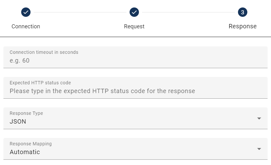
Connection timeout in seconds: Here the time limit (in seconds) for your REST call can be set.
Expected HTTP status code: Here you can set one or more expected status codes for your REST call.
Response Type: Here you can specify whether the output is in JSON format or returned as a file. An explanation regarding how to include files in REST calls can be found here.
Response Mapping: Here you can specify whether the returned data should be stored and used as process variables. The default setting is Automatic. If you select None, the response will not be processed as process variables. All response codes are accepted.
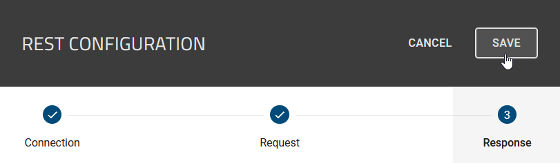
Click Save in the top right corner to save your configuration. If you do not want to save your changes, select the X icon located directly beside it, to close the dialog.
Regardless of the Response Mapping, a _response variable is stored, allowing you to access the request header and HTTP status code. If you have configured multiple service tasks, the _response variable will be overwritten after each execution. You can access the _response variable, for instance, through _response.headers.NAME[0] or _response.headers["NAME-NAME"][0] for keys with a hyphen. All response codes are accepted.
You can also process JSON objects and arrays in the response of the REST call in different formats. The system stores each element in the JSON object returned by the REST endpoint in the _response.body variable.
Note
If a service task with REST call returns an error status code such as 4XX or 5XX, GBTEC Work Orchestrator does not store information from _response.headers. The system then only stores _response.statusCode.
Hint
You can only use the _response variable for the active main process and its subprocesses.
Note
If you use a REST call, the system automatically follows HTTP redirects with the status codes 301, 302, 307 or 308. The REST call is successful even if the REST endpoint redirects to a new target address. The process receives the response from the target server as usual.
Warning
The system automatically sets tasks that were active during a system restart to error status. This applies to both script and service tasks, since the restart prevented them from completing. The system assigns these tasks to the responsible users and triggers an email notification. You can restart these tasks as usual.
How can I test my configured REST call query?
As a user with the ProcessApp Creator user role, you can test your configured REST call. To do this, you need to be in GBTEC Process Design. If you are currently in GBTEC Work Orchestrator, you can switch to GBTEC Process Design by using the Process Design focus in the focus drop-down menu in the header. Click on the Diagrams menu item in the left menu bar. You can either create a new diagram or check out an existing diagram. Open a diagram. To define the REST call, your diagram has to be marked as executable process. The activity type of the task must be set to Service.
After you have configured a service task, you can use the Test function to check your configuration directly. To do this, right-click on the activity and select Service configuration. A dialog opens where you can choose the type of service configuration. To test a REST call, click on the REST option. You do not need to deploy the process first.
In the configuration area of the service task, you will find the Test button after entering the REST configuration. This button runs the currently configured REST call with the specified parameters.
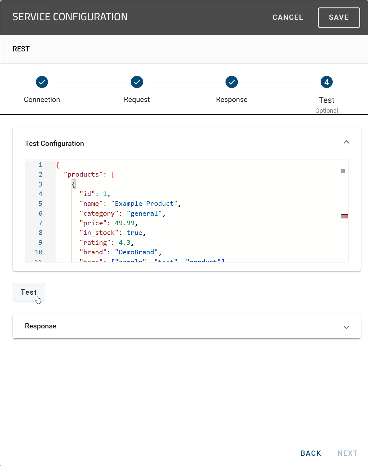
Select the Response button to see the result of the REST call after the test. A confirmation message appears if the call was executed successfully. If there are incorrect settings, for example due to an invalid URL or missing parameters, an error message appears instead.
If you use process variables in the REST configuration, you can store sample values in the test dialog. The system uses these values automatically during the test so that you can test the call with realistic data.
Note
The test runs only with the currently configured parameters. It does not require a process instance.
How can I use variables to create dynamic REST calls?
As a user with the ProcessApp Creator user role, you can create dynamic REST calls by using process variables. Use your process variables in the Request body of the REST configuration. List the variables as follows: {{VariableName}}.
For example, if you used the GET REST call to get an employee’s name and age, you can use these values as variables in the following REST call. The result of the first GET REST call could be: {"name": "John Doe", "age": 35}. You can then use these variables and their values in the following POST REST call within the field Request body (if you select JSON in the Body field) as follows: {"managerName": "{{name}}", "managerAge": "{{age}}"}.
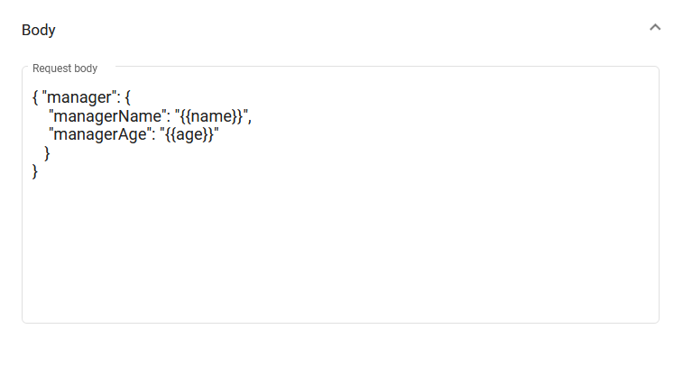
You can also use variables in the connection or response.
How can I filter and rename JSON responses in manual mapping?
As a user with the ProcessApp Creator user role, you can control the returned data in a REST configuration by filtering JSON responses and renaming variables individually. To open the REST configurator, you must be in GBTEC Process Design. If you are currently in GBTEC Work Orchestrator, you can switch directly to GBTEC Process Design by using the Process Design focus in the focus drop-down menu in the header.
Then open the menu item Diagrams in the left menu bar and select a diagram from the desired repository. Check out the diagram so that you can edit it.
To open the REST configurator in GBTEC Process Design, the diagram must be marked as an executable process. The activity must be of type Service. Then right-click the activity and select Service Configuration from the context menu.
Alternatively, you can open the editor by selecting the activity and choosing the Process Execution Editor in the Options panel in the right sidebar. There, you will find the Open Editor button, which opens the Service Configuration.
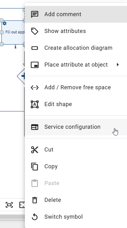
If you use a REST configuration and the response type is JSON, you can select the Manual option in the Response Mapping drop-down menu. This allows you to define which variables from the JSON response are included. To add a new variable, click the Add new empty row button. You can also rename the variables. This way, you control which data from the service response is included in the final payload.
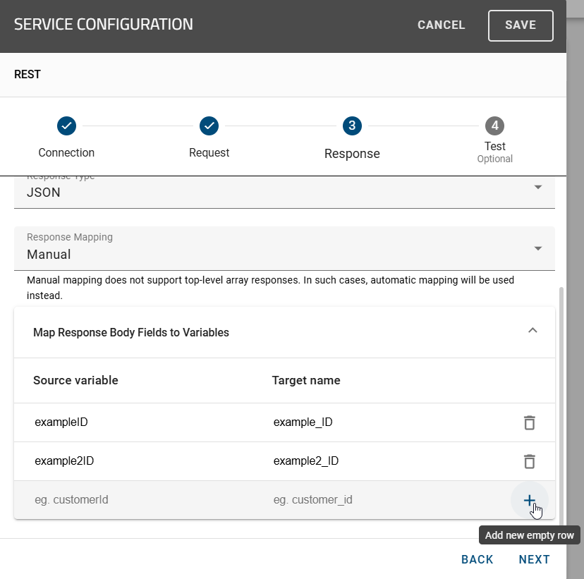
Define a list of source variables. These are the variables from the service response that should be used. Only the variables included in this list are added to the final payload. All other variables from the original response are excluded.
You can define a target variable for each included variable to rename it. For example, if you add the response variable customer_id to the list and define the target name customerId, the final payload shows only the variable customerId. The original name customer_id does not appear.
Hint
The system ignores variables that are not included in the filtered list. For example, if the service response contains a variable internalFlag that is not on the list, it does not appear in the final payload.
If you do not define any source variables in manual mapping mode, the resulting payload stays empty. This way, you control which data from the service response is processed further.
Hint
If you define a target variable without a matching source variable, the system ignores the mapping. If you define a source variable without a target variable, the editor automatically displays a placeholder based on the sanitized name of the source variable. After saving, the system uses this name automatically as the target variable.
To simplify variable selection, the editor provides an autocomplete function. After testing the REST configuration, you can start typing a variable name in the source variable field. For example, if you enter cus, the editor automatically shows the suggestion customer_id.
Hint
The target name may only contain letters (A-Z, a-z), numbers (0-9), and underscores (_). Spaces and special characters are not allowed. If you do not provide a target name, the system sanitizes the source variable automatically.
How can I use files in my REST calls?
As a user with the ProcessApp Creator user role, you can read the request body from a file when you configure your REST call. Add the file to the case as an attachment of a previous task. You can also define a REST call that returns a file. The system then saves this file as an attachment of the service task. To configure your REST call with files, follow these steps.
Request body as type file: If you want to read a document via a REST call and provide it as output to the user, you can do the following. In your diagram, model an activity marked as a Service task. On this activity, model a document and mark it as Output. Then, maintain the attribute Identifier of the document.
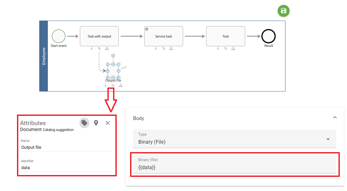
In the process flow, the service task has to occur after the task with the output. When you configure the REST call request, choose the type Binary (file) (or Multipart (file) if it is a data-form format) in the drop-down menu of the Body. Enter the identifier you defined previously.
If you use JSON Body Type with a matching Request Body (e.g., { “file”: “{{fileID}}” }), you can use file identifiers as placeholders in service tasks. The system replaces the placeholder with the file content of the identifier, encoded as Base64 data.
To upload a file in your running case, you need to add a document as an output in a previous task. When the service task is executed, it will retrieve the latest version of the file data, incorporate it into the JSON body, and automatically replace the placeholder.
File as response: Model the activity of your REST call in GBTEC Process Design with at least one document as output, to link a file returned by the REST call to your case. Maintain the Identifier attribute of the document to link it to the REST call response. In the REST configurator, choose the File option as the Response Type and enter the identifier in the field that appears. Enclose the identifier with two curly braces.
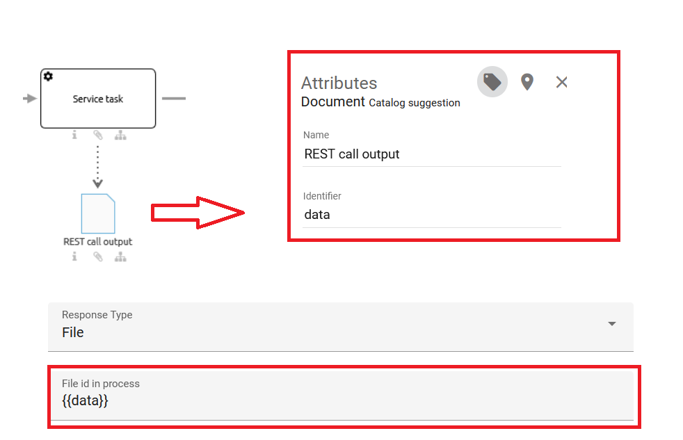
If the document’s Identifier matches a property of the REST call, and that property is formatted as Base64-encoded data, the system decodes the file content of the property and automatically adds it as an output document. This file takes the name of the existing file. If no name is available, the system automatically names the file after the identifier and the file type, for example .pdf. You can change the name if necessary.
If a REST service task provides a file with a defined identifier and you save it using a document output node, the system automatically creates a file variable with the file’s metadata. You can access and use this metadata within the process like any other file variable.
Warning
If you transmit Base64-encoded data with a defined identifier through a REST service task and store it using a document output node, the system no longer provides the original variable with the file content. The system removes the variable that previously held the file content and was linked to it. The file name consists of the transferred identifier and the matching file extension. You can access the metadata just like with any other file variable.
Note
If multiple files match an identifier and the REST call applies to them, the system attaches all files to the activity as output documents for Base64-encoded data.
After the REST call has been executed in your case, you can download the response file at the service task just as if it was uploaded manually.
How can I define multiple values as expected response status codes for REST calls?
As a user with the ProcessApp Creator user role, you can define multiple values as expected response status codes for REST calls. The configuration takes place in GBTEC Process Design. If you are currently in GBTEC Work Orchestrator, you can switch to GBTEC Process Design by using the Process Design focus in the focus drop-down menu in the header.
Click on the Diagrams menu item in the left menu bar. You can either create a new diagram or check out an existing diagram and open it. Then right-click the activity and select Service configuration. A dialog opens where you can choose the type of service configuration. Click on the REST option. Then go to Response. In the Expected HTTP status code input field, you can define multiple status codes. You can use both fixed status codes (e.g., 200) and regular expressions such as 200|201 (both codes apply), 20. (all codes from 200 to 209 apply), or combinations of these values.
If the received status code matches the defined pattern, the system treats the response as successful. Otherwise, it treats the response as an error.
Note
The pattern also accepts numbers, dots and pipes.
Reports
With the Reports option in the configuration dialog of the service task, you automatically create an output document in PDF or DOCX format instead of assembling it manually.
How can I automatically create an output document?
If you have modeled a service task, you can configure the report configuration for document creation in the editor.
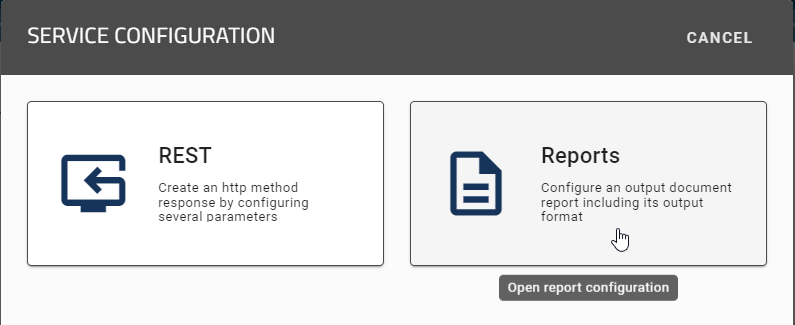
Selecting the REST call option starts the REST configuration. Alternatively, selecting the Reports option starts the report configuration, where you can specify the output format (PDF or DOCX).
If the report task contains an input with an attached file in your configured default language in DOCX format, the system uses this file as a template for the report. If the report task has an output and the system executes it, it adds the result to the output. The name of the output file matches the name of the template file.
Hint
If the input or output is missing or the input has no attachment, the system does not create the report and marks the task as an error.
If the input contains a Design Document but no Instance Attachment, the Design Document is the template for the report. If the input contains both a Design Document and an Instance Attachment, the Instance Attachment is the template.
Image Recognition
With the Image Recognition option in the configuration dialog of the service task, you extract data from an uploaded image, for example an invoice, without entering it manually.
How can I analyze and extract data from an image?
As a user with the ProcessApp Creator user role, you can extract and analyze data from an image with a service task. For example, you can extract specific content such as an address, an IBAN or amounts from an invoice. To do this, click on the Image Recognition option. There you upload an image and then configure fields for the data output. Specify a field ID, a name, a data type and a description of the desired content for each field.
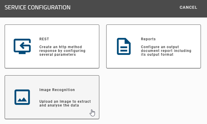
After you have selected the Image Recognition option, a dialog opens. There, you upload an image file on the left side of the screen. You can replace the uploaded image at any time by uploading a new image or dragging and dropping it over the existing one. To remove the image, click on the trash can symbol or on the remove image button.
On the right side of the screen, you add and configure variables for data extraction. Specify a Field ID, a Name, a Data type and a Description (Prompt) for each variable. This defines exactly which information the system extracts from the uploaded image file.
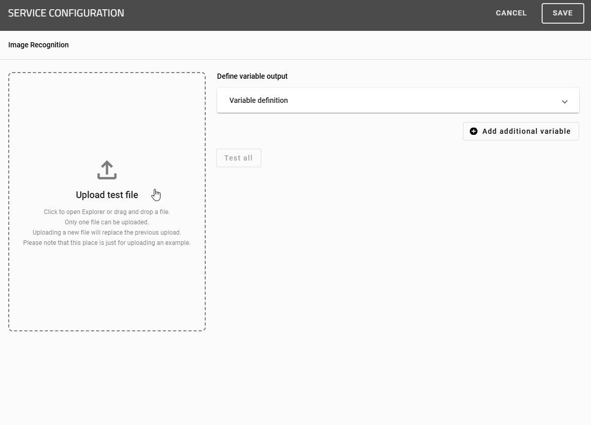
The following input fields are available for this purpose under Define variable output:
ID: ID for the variable (required field). This determines in which process variable the information is stored.
Label: The name of the variable is optional. If it is specified, it appears as the heading of the section. If there is no name, the system displays the field ID instead.
Data type: Specifies the type of information to be saved (Text, Number, Boolean). Other data types, such as Date, are currently not supported.
Prompt: Free text field in which you can formulate an instruction to our AI, e.g., “Give out only my IBAN” or “Read the address without the country.”
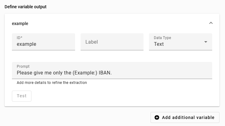
Each variable appears as a separate section in which you can perform an extraction using the Test button. As soon as you start a new test, the system overwrites the previous result. If you have created several variables, you can also check all configurations at the same time using the Test all button. If you would like to add another extraction, click on Add more variables to create a new line. The system displays the variables in alphabetical order and updates them in real time.
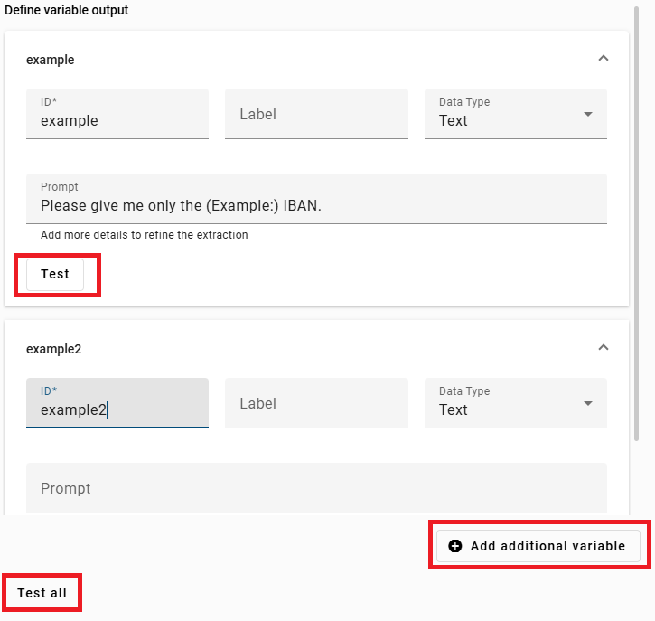
Hint
Duplicate IDs are not permitted. If you assign the same ID multiple times, an error banner appears, the affected sections open, and the system marks the affected fields with an error message. As soon as you change an ID (e.g., from “name” to “sender_name”), the conflict disappears.
Hint
The system grays out variables that have already been added in the process variable list. You cannot select these again. If you change the ID of a variable, the system displays it as available again.
Note
You can view the restrictions for uploading images via the following link.
MCP Server
An MCP server provides tools that you call directly in a service task. You need no technical knowledge of REST endpoints and configure no REST call of your own. A user with the ProcessApp Administrator user role defines which MCP servers are available to you in the Administration.
How can I call a tool from an MCP server?
If you want to model a service task with the ProcessApp Creator user role in GBTEC Process Design, first mark your diagram as an executable process. Then set the task type of the desired activity to Service.
Open the service configuration and select the MCP Server option.

Note
The MCP Server option is only available if at least one MCP server has been activated by a ProcessApp Administrator. Otherwise, you will see the message No MCP Servers Available.
In three steps, specify which tool you want to call. Use the Next and Back buttons to move between the steps. Your entries are retained when you move between steps.
1. Select Server

Select the desired MCP server from the list. The list contains only the MCP servers activated by a ProcessApp Administrator and is sorted alphabetically.
Click the Next button to go to the next step.
2. Select tool

Select one tool of the chosen MCP server. The name and a description are displayed for each tool. The tools are sorted alphabetically.
Note
If the selected MCP server does not provide any tools, you will see the message No Tools Available. In this case, choose a different server or contact your ProcessApp Administrator.
Click the Next button to go to the next step.
3. Define parameters

The system automatically displays a form with the parameters for the selected tool. It marks required fields.
You can also use process variables as placeholders in the parameters, for example {{VariableName}}. You can also combine static text and process variables, for example {{user.name}}.{{user.surname}}@gbtec.com.
Hint
The system displays only the top-level parameters of a tool. It does not support nested parameters.
If a required field is left empty or filled in incorrectly, the configuration is incomplete. The system then displays an error message.
Note
If the parameters of the selected tool cannot be configured, you will see the message Tool Configuration Not Available. In this case, choose a different tool or contact your ProcessApp Administrator.
When you have finished the configuration, click the Save button in the upper right corner. The system then saves the configuration in the matching attribute of the activity. Afterwards, you can close the service configuration using the X icon located directly beside it.
How can I set up an automatic time event?
Start Timer Event
In GBTEC Work Orchestrator, processes can be started either manually or automatically via a start timer event. Such an event makes it possible to begin the process at a set time and, if required, on a regular basis. This function is only available for BPMN diagrams and is not meant for EPC modeling.
Hint
Please note that start timer events are only run in the production environment, i.e. for published processes. In the test and development environments, no processes are started according to the Cron definition explained below. However, processes with a start timer event can be manually started in these environments, for example, for testing purposes.
Note
Please note that start timer events can be triggered manually in both the Public workspace and the Preview stage. However, this does not apply to the Publication stage. Therefore, if a start timer event in a published process needs to be triggered manually, a manual start event must also be modeled.
If you are currently in GBTEC Work Orchestrator, you can switch to GBTEC Process Design by using the Process Design focus in the focus drop-down menu in the header. Click on the Diagrams menu item in the left menu bar. You can either create a new diagram or check out an existing diagram. Open a diagram and select the start event. In the Details panel in the right sidebar, go to the attribute group Typing and set the event type to Timer.
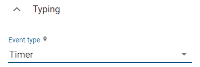
Then, right-click the start event to open the context menu. Select Start event settings.
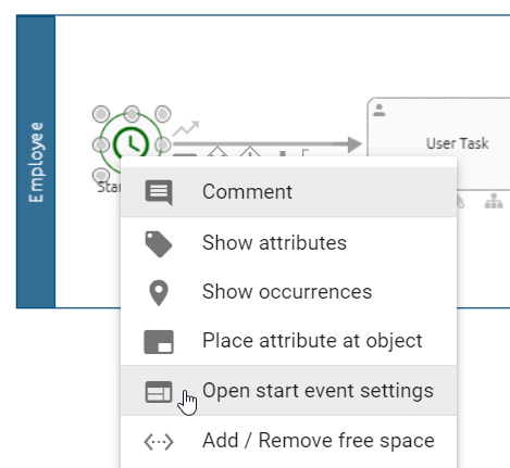
This opens a dialog. In the Starting timer configuration field, you can enter a Cron expression to define when new cases of the process are started automatically in GBTEC Work Orchestrator.
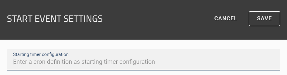
Select Save to save your settings and close the dialog. If you do not want to save your changes, select Cancel.
As soon as your process is published, a new case is started automatically each time the timer is triggered. Each case is named after its start time, and the involved roles are assigned according to their default staffing. Please note that the case does not have an owner. This means that tasks without default staffing must be delegated manually. If no responsible user is assigned to a started task, the task must be delegated before you can complete it.
Warning
If a section of a case that contains only automatic tasks is run ten or more times in succession, the entire case is automatically stopped for safety reasons. The affected task can be restarted manually. This resets the run counter. If more runs are required in certain cases, you can adjust the maximum number of allowed runs in the Process Execution Editor. By default, the maximum number of runs is ten, and at least one run must be possible.
Note
If the diagram is depublished or is no longer marked as executable, automatic case creation stops.
Tip
ProcessApp Administrators can edit the case name in the process variables.
Cron Expression:
A Cron expression is a chain of fields which are separated by blank spaces. The fields define the time units in the following order:
<Second> <Minute> <Hour> <Day-Of-Month> <Month> <Day-Of-Week>.
A field can be made up of one or a combination of the following valid values and/or characters.
Field |
Range of values |
Valid characters |
|---|---|---|
Second |
0-59 |
, - * / |
Minute |
0-59 |
, - * / |
Hour |
0-23 |
, - * / |
Day-Of-Month |
1-31 |
, - * ? / L W |
Month |
0-11 or JAN-DEC |
, - * / |
Day-Of-Week |
1-7 or SUN-SAT |
, - * ? / L # |
Hint
Please note that support for using both a day-of-week and a day-of-month parameter at the same time is not available.
By combining these characters, you can configure the start event (“set a timer”) in such a way that cases are started at recurring times. The following section gives an explanation of the possible characters based on this page.
Tip
On Freeformatter.com, you can find a free tool to generate Cron expressions.
- *: The timer is set for every <time-unit>.
Example: ‘*’ as <Month> means that a new case is started every month (JAN-DEC).
- ?The timer is set on each <Day-Of-Week> resp. on each <Day-Of-Month>.
Example: ‘?’ as <Day-Of-Week> means that a new case is started regardless of the day of the week.
- -The timer is defined for a time span (from-to).
Example: ‘MON-SAT’ as <Day-Of-Week> means that a new case is started on each working day.
- ,The comma can be used to enumerate multiple values for one time unit. List the values without blank spaces.
Example: ‘8,15’ as <Hour> means that new cases are started at 8 AM and 3 PM.
- /The timer can be defined using individual increments.
Example: ‘1/7’ as <Day-Of-Month> means that new cases are started every 7 days starting on the first day of a month.
- LThe last value of the <time-unit>. It is also possible to combine this character with numerical values, e.g. using ‘L-2’ to get the second last value.
Example: ‘L’ as <Month> means that a new case is started on the last day of each month, i.e. on 31.01, 28./29.02., 31.03. etc.
- WThe timer is set dynamically on the nearest week day (MON-FRI).
Example: ‘1W’ as <Day-Of-Month> means that a new case is started on the nearest week day to the first day of the month. If the first day of the month is a Saturday, the new case will already be started on Friday. If the first day of the month is a Sunday, the case will be started on the following Monday.
- #<n>The timer is set to the <n>-th occurrence of the <Day-Of-Week> where <n> is a natural number.
Example: ‘2#1’ as <Day-Of-Week> means that a new case is started on the first Monday of a month.
Hint
Note that the system works out the case start times in the time zone of the server. If your local time is different from the server time, be sure to take the difference into account when defining the Cron expression.
For example, if you want a case to start at 8 AM in Germany (UTC+1), but the server is located in the UTC+0 time zone, you have to set the timer to 7 AM.
The following three examples show some possibilities to configure a recurring start using the values and characters:
- 0 30 8 ? * MON-FRI
New cases start each day from Monday to Friday at 8 AM.
- 0 0 15 1 * ?
New cases start each first day of a month at 3 PM.
- 0 0 12 ? JAN,JUN 2#1
New cases start at the first Monday of January and June at 12:00 PM.
Intermediate Timer Events
You can pause your case for a set time before it continues. This can be useful, for example, when you are waiting for a payment confirmation. You can set the case to continue after 3 days.
Hint
Please note that intermediate timer events only run in the productive environment (i.e. for published processes). The ISO 8601 definition described below does not apply in the test or development environment.
Hint
Please note that intermediate timer events only work in BPMN modeling, not in EPC modeling.
If you are currently in GBTEC Work Orchestrator, you can switch to GBTEC Process Design by using the Process Design focus in the focus drop-down menu in the header. Open the corresponding diagram in GBTEC Process Design. In the attributes of the intermediate event, select the event type Timer in the attribute group Typing.
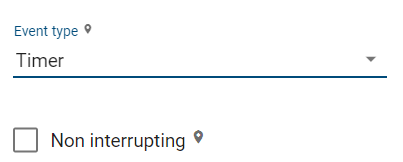
Then right-click the symbol to open the context menu of the intermediate event. Choose the option Intermediate event settings.
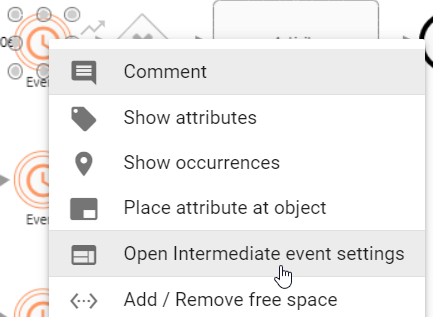
Selecting this option opens a dialog. In the Timer definition field, you can define the duration using the ISO8601 format or a variable. This defines when the case continues in GBTEC Work Orchestrator.
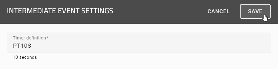
Select Save to save your configuration and close the dialog, or use the Cancel button to discard your changes.
Once an intermediate event is integrated into the corresponding process diagram, it becomes visible in the process flow. You will then see the publication date and time for the intermediate event and the configured timing there.
When the configured time is reached, the intermediate timer event is marked as done, and the date and time of completion are displayed.

When entering a variable as a placeholder, you can choose between a JUEL expression and String replacement. You choose the variant in the drop-down menu at the top of the Process Execution Editor in the Options panel on the right.
Please note that both variants are not supported at the same time. Diagrams that were created before version 8.0.0 automatically use the previous string replacement logic. For newly created diagrams, however, the JUEL variant is preselected by default. You can adjust the selected option at any time, but switching new diagrams to String replacement is not recommended.
Tip
You can find more information about JUEL expressions here.
Warning
When selecting an intermediate time event in the process flow of a process diagram, only the name and description of the event are displayed in the task form.
After the diagram has been published, the case will only continue when the intermediate event is reached and the configured time is triggered. If the case is in a different stage, it continues immediately. This also applies if the time is missing, incorrect, or in the past.
As a case owner, ProcessApp Administrator, or ProcessApp Creator (for ProcessApp Creator, this option is only available in the development and test environment), you also have the option to manually end a time-based intermediate event before the configured time has elapsed. This lets you continue the process earlier if the timer event is no longer relevant or if you require immediate further processing. To do so, click the Proceed now button in the task form in the right sidebar.

Note
If the configured time is reached while the servers are down, the case continues after the servers restart.
Hint
If an active case is aborted, all timers stop.
ISO8601 format:
An ISO8601 format is a string of fields that specifies the time span of a time interval and is represented by the format P(n)Y(n)M(n)DT(n)H(n)M(n)S. The capital letters P, Y, M, W, D, T, H, M, and S are identifiers for each of the date and time elements and are not replaced, but can be omitted.
P : is the duration designator (for period) at the beginning of the duration representation.
Y : is the year designator that follows the value for the number of years.
M : is the month designator that follows the value for the number of months.
W : is the week designator that follows the value for the number of weeks.
D : is the day designator that follows the value for the number of days.
T : is the time designator that precedes the time components of the representation.
H : is the hour designator that follows the value for the number of hours.
M : is the minute designator that follows the value for the number of minutes.
S : is the seconds designator that follows the value for the number of seconds.
Note
Please note that the n is replaced by the value for each of the date and time elements that follow the n.
The fields define the time units in order:
<year> <month> <day> <hour> <minute> <second> <millisecond>.
Each field can contain one or a combination of the permitted values and/or characters.
Representation according to ISO 8601 |
Value range |
|---|---|
Year (Y) |
YYYY, four digits, shortened to two digits |
Month (M) |
MM, 01 to 12 |
Week (W) |
WW, 01 to 53 |
day (T) |
T, day of the week, 1 to 7 |
Hour (h) |
hh, 00 to 23, 24:00:00 as end time |
minute (m) |
mm, 00 to 59 |
second (s) |
ss, 00 to 59 |
Decimal fraction (f) |
Fractions of a second, any accuracy |
Examples:
PT15S - 15 seconds
P14DT1H30M - 14 days, 1 hour and 30 minutes
P3Y6M4DT12H30M5S - 3 years, 6 months, 4 days, 12 hours, 30 minutes and 5 seconds
Subprocesses
How can I start subprocesses from a process?
If you want to start another process from within a case, you can use call activities. This lets you start new child cases. If you want to call a process in GBTEC Work Orchestrator, it also needs to be marked as executable. If the called process is not marked as executable, the task will be treated as a normal user task and must be completed manually.
Here you can find an explanation of how to work with a call activity.
You model this in GBTEC Process Design. If you are currently in GBTEC Work Orchestrator, you can switch to GBTEC Process Design by using the Process Design focus in the focus drop-down menu in the header. Add an activity to your diagram. In the Details panel in the right sidebar, go to the attribute group Typing and set the process type to Call activity.
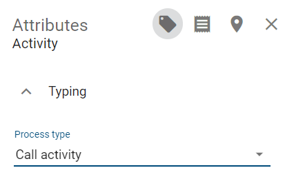
Right-click your call activity to open the context menu. Select Open Call activity settings.
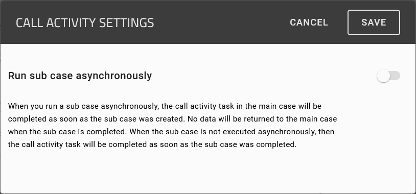
Here you can choose whether your call activity shall be synchronous or asynchronous.
Synchronous call activities will be started immediately and pause the main case. The process variables are passed to the sub case. After the sub case is completed, the process variables are passed back to the main case. If the ProcessApp Administrator manually completes the synchronous call activity, nothing will change in the existing sub case and it can continue to be processed.
Asynchronous call activities will also be started immediately, but will not pause the main case. The process variables will also be handed over to the sub case at the start, but they will not be passed back when the sub case completes. You can continue working on the main case before the sub case is completed. If the main case is archived, nothing will change in the existing sub case, and it can continue to be processed.
In the attribute Subprocess of the call activity, select the process that you want to link. The following example shows the attribute of the call activity “Create custom-made product”, which is part of an order process. The subprocess diagram “Custom-made product” is an executable BPMN diagram.
If the order process is executed in GBTEC Work Orchestrator, a new case is automatically started for the called process as soon as the task of the call activity is started. The case is named after the call activity plus “- name of the main case”. In the example, the call activity “Create custom-made product” of the main case “Order 2503” started a new case of the process “Custom-made product”.
Main case “Order 2503”:
Sub case (new case of the process “Custom-made product”):
Max Mustermann is responsible for the tasks of the sub case because he is the default assignee of the corresponding role. The system is the creator of the subprocesses started by call activities.
How can I use input and output documents for my subprocess?
Once an input document has been modeled for a call activity, the uploaded document is available for use in the subprocess. If the identifier of this document matches the identifier of the input document of the corresponding call activity in the main process, the document becomes available in the subprocess.
Hint
You can also model several input documents. These are then all available in the subprocess. For each case, the document uploaded most recently is used as the input document.
The subprocess can either overwrite the input or leave it unchanged. This applies both within the same case and for inputs from a main process. It also applies when parallel paths in the process partly lead to overwriting and partly to not overwriting.
You can also model one or more output documents in a call activity to transfer a file from the subprocess to the main process. If the subprocess creates a file variable whose identifier matches the identifier of an output document of the call activity, this file is transferred to the main case once the subprocess has finished. The name, size, and file type of the file are preserved. The file is then available for further tasks in the main process.
If a file variable with the same identifier already exists in the main case, it is replaced by the file from the subprocess. This corresponds to manually uploading a new file using a form field of the type file.
If the Identifier of the file created in the subprocess does not match any of the modeled output documents, the file is not transferred to the main process through the output document assignment.
Hint
You can also model several output documents with different identifiers. Each matching file is then assigned to the corresponding output document. The respective metadata is preserved in this case.
Note
Please note that, regardless of whether output documents are modeled, all process variables of the subprocess case are always transferred to the main case. If a process variable from the subprocess has the same identifier as an existing process variable in the main case, it overwrites that variable in the main case.
How do I define a correlation key for a throwing event?
In a process initiated by a throwing event, there is an option to access specific configurations through the Details menu of the editor. Here, you can set a JUEL expression as a correlation key.
When the predefined throwing event occurs, a message is automatically generated. This message contains a specified event ID and the previously defined correlation key. At the same time, when the event occurs, the associated process step is triggered and marked as completed.
Note
The defined correlation key is retrievable in the context of the process instance.
Tip
Correlation keys can also be used within BPMN message events. Examples of correlation keys include order.orderId and user.identity.email. This ensures that an incoming message is matched not only by its name but also by the specific business data that identifies the corresponding process instance. When a message with a matching correlation key arrives, the intermediate event in the process is triggered, the waiting process instance resumes, and the subsequent task is automatically activated. For example, if a process is waiting at an intermediate message event correlated by order.orderId and a message with the same order ID arrives, the waiting process instance resumes at that point.
How can I configure the repeat limit for fragments in the Process Execution Editor?
In the Process Execution Editor, you have the option of setting fragment repetitions in processes. To do this, you must be in the Public workspace area and have at least the Author user role. If you configure fragments in a process model, they can be executed multiple times. To avoid endless loops or unintentional continuous executions, a maximum execution limit per process instance can be defined in this editor. If this value is exceeded, the process pauses automatically and thus prevents incorrect or uncontrolled repetitions.
To do this, click in GBTEC Process Design on the Diagrams menu item in the left menu bar and select the desired diagram. Check out the diagram and navigate to the Options panel in the right sidebar. Then open the Process Execution Editor option. There you will find the configuration option Fragment execution limit per case.
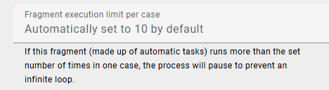
The input field Fragment execution limit per case is preset with the value 10 by default. In addition, a note is displayed that the process is stopped during automatic execution as soon as the specified limit is exceeded in order to avoid endless loops. You can adjust this value to define how many times a fragment may be executed per case.
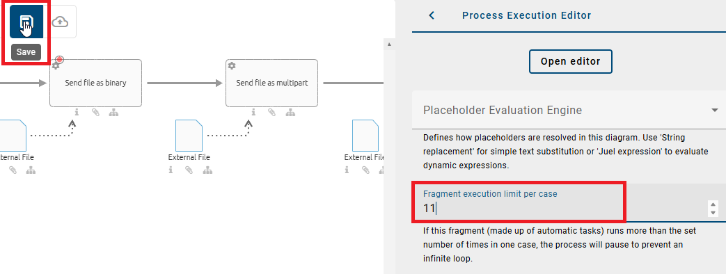
After entering and saving a valid value, the setting is saved in the process definition. When the process is executed later, the limit you have defined is used to check for too many repetitions and thus replaces the default value.
Note
Please note that only positive integers greater than 0 are permitted for input. If, for example, you enter 0, -5, a decimal number or a text, an error message will appear, prompting you to correct your entry. In this case, the configuration can only be saved after the error has been corrected.
How can I model activities with a (dynamic) due date?
You can model your activities with a dynamic due date. This means that the resulting tasks have to be completed in a certain number of days or on a certain date. An explanation of how to work with due dates in GBTEC Work Orchestrator can be found here
To do this, open the panel Options of the activity in the right side bar and select the option Process Execution Editor. There you can set the Due date of the element.
Here you can enter how many days after the start of the task or on what date the task is due. GBTEC Work Orchestrator will automatically calculate the correct due date.
Note
If you do not give any input in the field, the due date will be set to the same value as the case due date.
Tip
Declare at least one date field in advance in the form editor to determine a due date with this value as well.
Note
You also have the option of using JUEL expressions (Java Unified Expression Language) to define dynamic due dates. With these expressions, you can not only query simple variable values, but also specifically access individual values within complex variables. Further information about JUEL expressions can be found here.
In the following, some examples of how to determine the due date using at least one date field are provided. Here, two date fields are created in the form editor and declared with the IDs “DueDate1” and “DueDate2”. For these examples, DueDate1 is always set to 03/28/2023 and DueDate2 to 04/05/2023.
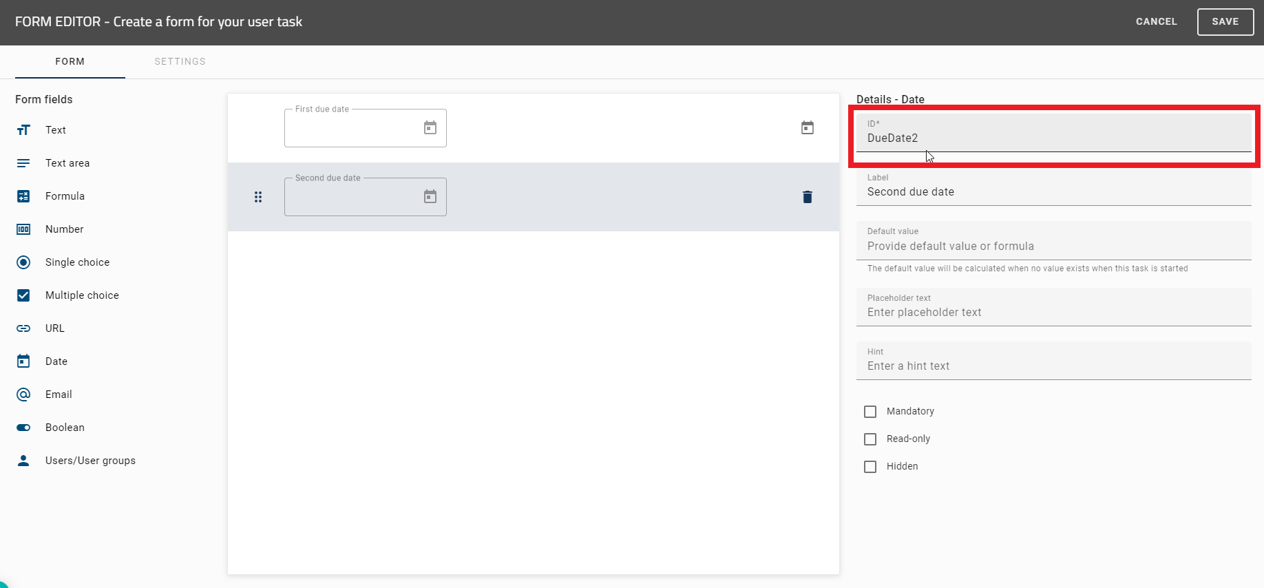
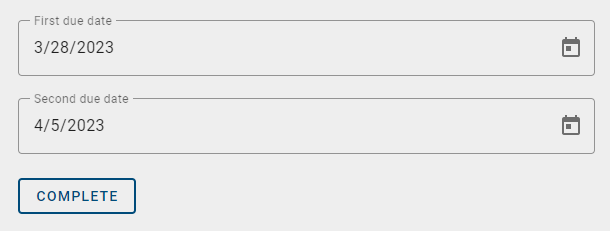
Hint
You can also determine dates in ISO 8601 format when using the form field Text and millisecond timestamps by using the form field Number through the following commands.
To move the due date by X days/weeks/months/years, you can use the commands:
nameID.plusDays(X).plusWeeks(X).plusMonths(X).plusYears(X)

nameID.minusDays(X).minusWeeks(X).minusMonths(X).minusYears(X)
nameIDhere stands for your declared date field ID.plusDays(X) / minusDays(X)allows you to move the due date back or forward by X days.plusWeeks(X) / minusWeeks(X)allows you to move the due date back or forward by X weeks.plusMonths(X) / minusMonths(X)allows you to move the due date back or forward by X months.plusYears(X) / minusYears(X)allows you to move the due date back or forward by X years.
Examples:
DueDate1.plusDays(4)
gives the output 04/01/2023.
DueDate1.plusWeeks(2).minusDays(1)
gives the output 04/10/2023.
DueDate2.plusYears(1).minusMonths(2).plusWeeks(3)
gives the output 02/26/2024.
DueDate2.minusWeeks(3).minusYears(1).plusDays(10).plusMonths(6)
gives the output 09/25/2022.
To set the due date to the first day of the month, you can use the command
.withDayOfMonth(X)
Set X to the number 1 to give the first day of the month as the output.
Examples:
DueDate1.withDayOfMonth(1)
gives the output 03/01/2023.
DueDate2.plusYears(2).withDayOfMonth(1)
gives the output 04/01/2025.
DueDate2.plusMonths(3).minusYears(1).withDayOfMonth(1)
gives the output 07/01/2022.
Alternatively, you can choose any number between 1-31 for X.
DueDate1.plusYears(1).minusMonths(2).withDayOfMonth(15)
gives the output 01/15/2024.
Hint
Avoid numbers above 28, since not every month has the same number of days. For a number higher than 28, proceed as in the next example.
To set the due date to the last day of the month, you can use the command
nameID.plusMonths(X).withDayOfMonth(1).minusDays(X)
where nameID stands for your declared date field ID.
Examples:
DueDate1.plusMonths(1).withDayOfMonth(1).minusDays(1)
gives the output 03/31/2023.
DueDate1.plusMonths(2).withDayOfMonth(1).minusDays(1)
gives the output 04/30/2023.
DueDate2.plusMonths(1).withDayOfMonth(1).minusDays(1).plusYears(3)
gives the output 04/30/2026.
DueDate2.plusMonths(1).withDayOfMonth(1).minusDays(2)
gives the output 04/29/2023.
You can also use an if-else-then-statement to determine the due date if the output is determined by a Boolean value. For this, you need the operators ? and :, and a TRUE and FALSE condition. In addition, at least two date field IDs must be declared.
To compare two dates with each other, use the command:
nameID_1.equals(nameID_2) ? X : Y
equals()is the command to compare two dates with each other.nameID_1 / nameID_2stand for your declared date field IDs.?terminates the request, followed by the TRUE and FALSE conditions.Xis the output if the request is TRUE.Yis the output if the request is FALSE.:is inserted to separate the TRUE condition from the FALSE condition.
Examples:
DueDate1.equals(DueDate2) ? 5 : DueDate1.plusWeeks(1)
gives the output 04/04/2023, because the condition is FALSE.
DueDate2.equals(DueDate1) ? DueDate2.plusWeeks(2) : DueDate2.minusDays(3).plusMonths(1)
gives the output 05/02/2023, because the condition is FALSE.
DueDate1.equals(DueDate2) ? 5 : 10
adds 10 days to the date when the task was created since the condition is FALSE. For example, if this date is set to 04/01/2023, the output will be 04/11/2023.
To check whether a date is before or after another date, you can use the following commands:
nameID_1.isBefore(nameID_2) ? X : Y

nameID_1.isAfter(nameID_2) ? X : Y
isBefore()checks if the date (nameID_1) is before the other date (nameID_2).isAfter()checks if the date (nameID_1) is after the other date (nameID_2).
Examples:
DueDate1.isBefore(DueDate2) ? DueDate1.plusMonths(1).withDayOfMonth(15) : DueDate2
gives the output 04/15/2023, because the condition is TRUE.
DueDate2.isBefore(DueDate1) ? DueDate2.minusDays(5) : DueDate2.plusWeeks(2).plusMonths(1)
gives the output 05/19/2023, because the condition is FALSE.
DueDate1.isAfter(DueDate2) ? 10 : DueDate2.minusMonths(1).withDayOfMonth(20)
gives the output 03/20/2023, because the condition is FALSE.
DueDate2.isAfter(DueDate1) ? 20 : DueDate2.plusYears(1)
adds 20 days to the date when the task was created because the condition is TRUE. For example, if this date is set to 04/01/2023, the output will be 04/21/2023.
Hint
If the output value of a TRUE or FALSE condition is a number, this number will always be added to the date on which the task was created.
How can I edit modeled tasks in the catalog?
As a user with the ProcessApp Creator role, you can open and edit task editors for modeled tasks in the Catalog in GBTEC Process Design. This includes editors for user tasks, script tasks, service tasks with REST calls, and send tasks. If you are currently in GBTEC Work Orchestrator, you can switch to GBTEC Process Design by using the Process Design focus in the focus drop-down menu in the header.
Open a diagram, check it out, and click on an empty area of the canvas. In the Details panel in the right sidebar, select the Automation attribute group and mark the process as an executable process. If needed, model your process and then select an activity. In the Typing attribute group in the right sidebar, choose a task type in the Task type field. Save your diagram and check it in using the Check In button.
If no Catalog item exists for this activity yet, right-click the activity in the checked-in diagram and select Suggest to catalog.
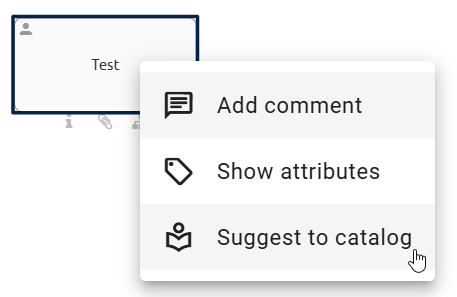
Once the Catalog item has been suggested, right-click the activity again and select Open in catalog. You are then taken to the details view of the selected activity in the Catalog. You can also open the Catalog via the Catalog menu item in the left menu bar.
In the details view, the Options panel in the right sidebar shows an additional option to open the editor for the selected task type.
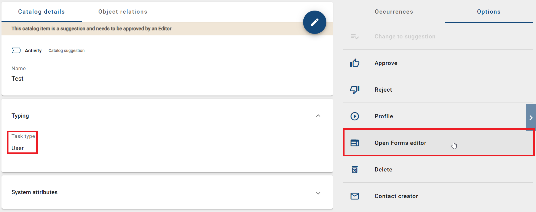
This option is available for both suggested and accepted Catalog items. Clicking it opens the corresponding task editor. The editor is synchronized with the diagram and can be adjusted centrally. This allows you to manage task configurations across multiple diagrams without checking out each diagram.
Hint
Please note that the option to open an editor is only available in the Public workspace stage. Make sure that you also have the required role in GBTEC Process Design.
Development and test environment
In addition to the productive environment where processes can be executed, GBTEC Work Orchestrator offers two more environments where processes can be examined and tested while the diagram is still being modeled in GBTEC Process Design.
A process in the studio or development environment is based on the version of its related diagram in the public workspace. If you have modeled a diagram as executable process in GBTEC Process Design, it will be visible in the development environment right after check-in.
As soon as this diagram is available in preview stage of GBTEC Process Design, it also appears in the test environment.
The development and test environments perform as follows: If there is a former version in the respective environment, it will be replaced when the corresponding diagram in the public workspace or preview has changed. All existing cases of the process in the environment will be deleted. This helps authors to view and examine changes in the process right after modeling the corresponding diagram.
Which environments are existing?
The execution of established processes is done in the productive environment of GBTEC Work Orchestrator. This environment is accessible for all registered users of GBTEC Process Design. A process is displayed and usable in the productive environment if the corresponding diagram is published in GBTEC Process Design.
There are two more environments: the development and the test environment. Users with the user role ProcessApp Creator or higher can access these environments to test processes before publishing them. More information can be found in the chapter “Development and test environment”.
How can I change the environment?
You are viewing the productive environment if the URL of your browser contains the keyword “app”:
https://XXX/process-execution/app/...
You can access the development or test environment by modifying the URL. Add the keyword “studio” or “test” behind .../process-execution/:
Use
https://XXX/process-execution/studioto enter the development environment/the studio.Use
https://XXX/process-execution/testto enter the test environment.
The following table serves as a short overview of the environments:
Development environment |
Test environment |
Productive environment |
|
|---|---|---|---|
Diagram version |
public workspace |
preview |
publication |
URL key word |
|
|
|
How can I test a process while it is modeled?
If you define a process by modeling a diagram in GBTEC Process Design, you can test it directly. You simply have to mark the diagram as an executable process in the attributes.
As soon as you check-in the diagram, the Test ProcessApp button appears.
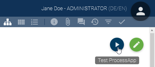
Select the button to open the studio of GBTEC Work Orchestrator in a new browser tab. A new case of the modeled process will be created there automatically. The case name is maintained by the system with the name of the process and a timestamp. All roles will be assigned to you (even if the roles have a default allocation). This enables you to quickly test the process flow, as no further manual configuration of the test case is required.
How can I test a process before publication?
You can test new processes modeled in GBTEC Process Design while the diagram is still in the preview stage. This allows you to create a final test case while reviewing the diagram before it is published. Please note that the diagram must be marked as an executable process in the attributes. If you are currently in GBTEC Work Orchestrator, you can switch to GBTEC Process Design by using the Process Design focus in the focus drop-down menu in the header.
In the diagram view, you will find the button Test ProcessApp.
Click the button to open the test environment of GBTEC Work Orchestrator in a new browser tab. A dialog for creating a new case for the defined process opens there. Follow the same steps as in the production environment to configure your test case.
How can I define a default role allocation for the process instantiation?
In GBTEC Process Design, you can assign users or organizational units to roles so that they are automatically set during the process instantiation in GBTEC Work Orchestrator. If it is known in advance that the same users or organizational units are almost always responsible for all cases of a process, you can make process instantiation faster for that particular process.
To use this function, navigate to the relevant role in the desired diagram in GBTEC Process Design. In the Staffing attribute enter the user or organizational unit. You can find this attribute within the attribute group Automation.
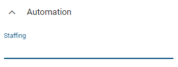
After the users, user groups, and organizational units have been entered, the diagram has to be published afterwards to apply the changes to the process in the productive environment. Once the new version of the diagram has been published, the user or organizational unit is assigned to the role of Responsible by default during process instantiation.
Tip
During the instantiation process the allocation can then still be changed if needed.
Note
If no user or user group was defined for a role when the case was created, the case creator is responsible for executing the task as soon as the case is started.
How can I set up a case creation restriction?
In GBTEC Process Design, you can define a case creation restriction for diagrams that are executed in GBTEC Work Orchestrator. This allows you to decide individually for each process which users can create new cases. If you are currently in GBTEC Work Orchestrator, you can switch to GBTEC Process Design by using the Process Design focus in the focus drop-down menu in the header.
To define such a restriction, open the Details of the relevant diagram. You will find the attribute Case creation restriction in the attribute group Automation.
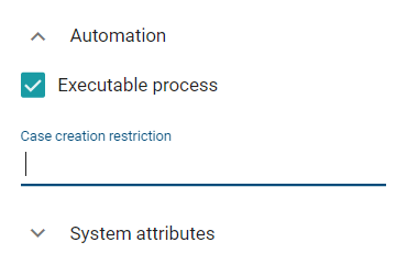
Similar to the diagram or repository access restriction, you can enter the names of multiple users or entire user groups. As soon as you start typing in the input field, a list of suggestions is displayed from which you can choose.
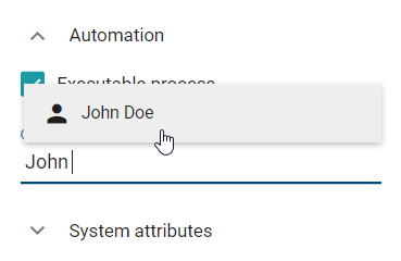
Once a case creation restriction has been defined and the diagram meets all requirements to be displayed in GBTEC Work Orchestrator, the restriction works as follows:
All users included in the case creation restriction can create cases for the corresponding process as usual. The same applies to users who are members of user groups included in the case creation restriction.
All other users will still see the process, but they will not be able to create cases for it. This means that the Create a new case function will not be displayed either in the menu of the corresponding ProcessApp or in the case list of the process.
How can I set a retention period for the archived cases of my process?
If you model a process in GBTEC Process Design, you can configure a retention period for all archived cases of the process. When a case is archived, it is stored in the archive until the retention period expires. Then the case will be automatically and irrevocably deleted. You can set the time period in the attribute Retention period, which is part of the attribute group Automation. Enter a time period in days, e.g. “365” in order to store the archived cases for one year.
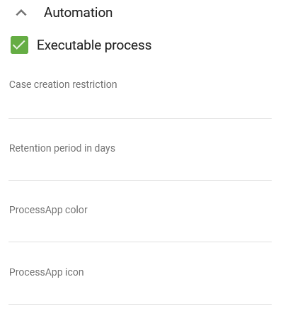
When the retention period of a case expires while you are viewing the list of archived cases, the case will be removed from the list and you will be informed by a message. In case you are viewing the process flow of an archived case and the retention period of this case expires, the system deletes the case and you will be redirected to the case list of the corresponding process. You receive a message informing you of this automatic action.
Warning
Maintaining a retention period leads to the irrevocable deletion of archived cases. For each case, the period starts to expire from the time it was moved to the archive.
How can I add a process to a ProcessApp Collection?
The assignment of a process to a ProcessApp Collection takes place in GBTEC Process Design. If you are currently in GBTEC Work Orchestrator, you can switch to GBTEC Process Design by using the Process Design focus in the focus drop-down menu in the header.
In GBTEC Process Design, open the diagram of the process you want to add and open its attributes. In the attribute group Automation, you will find the attribute ProcessApp Collections.
Here, you can enter one or more ProcessApp Collection IDs.
How can I model the process flow with gateways?
Usually, a process does not follow a single linear flow. Based on decisions, the process path can split into multiple flows, which may also run in parallel. In GBTEC Process Design, you can model this with sequence flows and gateways. In a concrete case in GBTEC Work Orchestrator, gateways result in decisions or introduce parallel flows (and reunite them).
You can use the following three types of gateways:
Exclusive gateway: After this gateway, exactly one sequence flow is followed. You can automate the decision of which one to choose in a particular case.
Inclusive gateway: After this gateway, one or more of the following sequence flows can be executed.
Parallel gateway: With a parallel gateway, all subsequent sequence flows are executed.
Note that it is possible to model multiple outgoing sequence flows at an activity without using gateways.
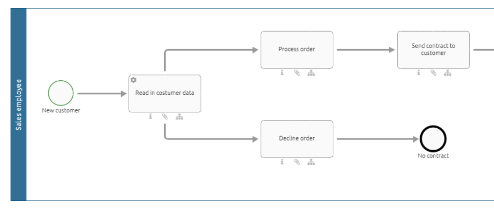
In the case of the image above, you have to define expressions for an automatic decision about the course of the process flow. Otherwise, the process will get stuck. If you do not want to work with expressions and automated decisions, you must model the process with a gateway (see below). The case owner then receives a task for manual decision.
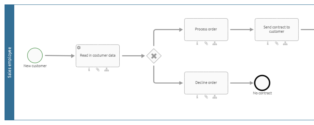
How can I model an automated decision?
During the execution of a case, decisions can be made automatically to determine the next step in the process. To use this function, you must define expressions in the sequence flow in GBTEC Process Design. These expressions specify the conditions under which a specific path is selected. If you are currently in GBTEC Work Orchestrator, you can switch to GBTEC Process Design by using the Process Design focus in the focus drop-down menu in the header. Click on the Diagrams menu item in the left menu bar. You can either create a new diagram or check out an existing diagram.
Open the diagram in GBTEC Process Design that is used as the basis for the process in GBTEC Work Orchestrator. For each sequence flow after a split gateway, define an expression that determines when the next path is followed. To do this, select the corresponding sequence flow. In the Automation section of the sequence flow attributes, you will find the input field Expression.
Note
If you use a parallel gateway in your process, you do not need to define expressions, since every outgoing path is executed.
Here you can define your expression using Java syntax. An overview of the notation can be found in the table below. The return value of the expression must be of type boolean. The conditions are always based on process variables, which receive their values before the gateway is reached in the process flow in GBTEC Work Orchestrator. For example, you can use process variables from previously executed REST calls or from previously executed rule-based tasks.
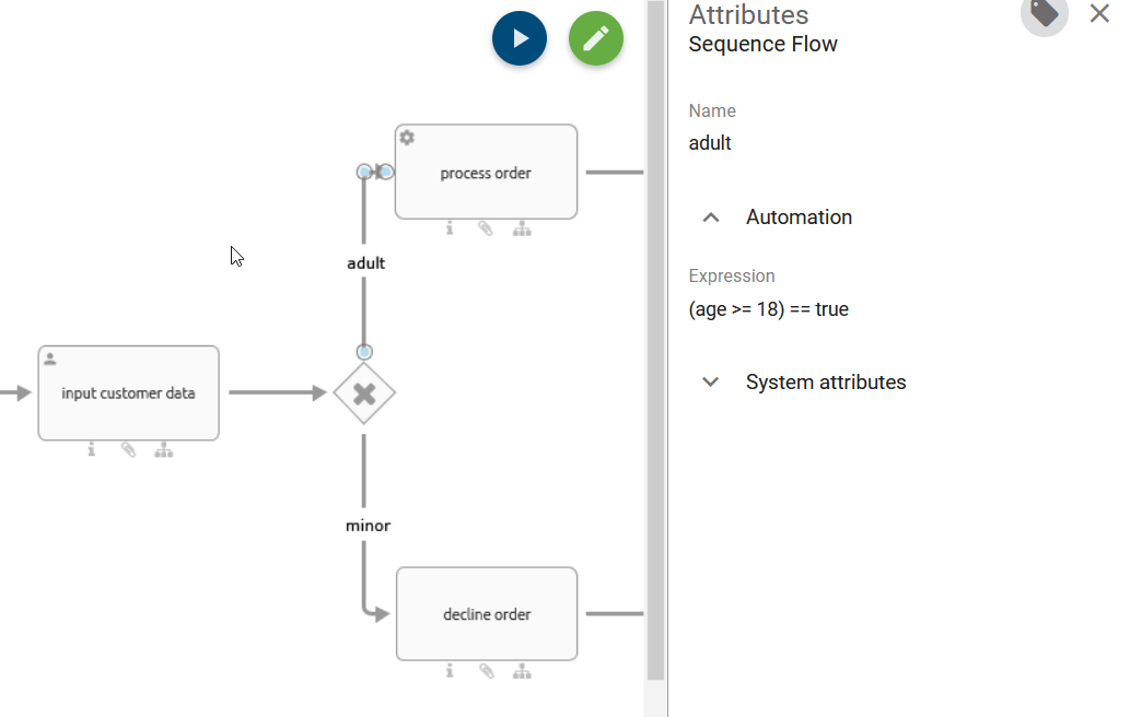
Symbol |
Description |
Symbol |
Description |
|---|---|---|---|
|
logic and |
|
smaller than |
|
logic or |
|
smaller or equal |
|
comparison of expressions (is used with |
|
equal |
|
expression is true |
|
not equal |
|
expression is wrong |
|
bigger or equal |
|
bigger than |
For example, the expression (age >= 18) == true checks whether the value of the process variable age is greater than or equal to 18. If this is true, the corresponding path is selected.
You can also use JUEL expressions (Java Unified Expression Language) to define expressions. You can query both simple first level variables, such as user.identity == 'email@gbtec.com', as well as more complex variables with multiple levels that refer to specific properties of the variable. For example, you can query user.identity.email == 'email@gbtec.com'. Further information about JUEL expressions can be found here.
Warning
Please note that with JUEL expressions, such as:
{{budget > 1000 ? "budget exceeded" : "budget not exceeded"}},
results can also be different from true or false.
As soon as you have defined your expressions and the diagram meets all requirements, you can use the respective process with the automated decision in GBTEC Work Orchestrator.
In GBTEC Work Orchestrator, when the value of a process variable changes, for example due to a change within a decision table or due to a manual change by a ProcessApp Administrator, all expressions which include that process variable are checked for their return value.
If the first expression in an Exclusive Or gateway returns true, the system selects and shows the corresponding path in the process flow of the case. If the expression returns false, the system checks the next expression.
You can also use an Exclusive Or gateway to check whether a file was uploaded in an earlier task. In the diagram, at least one activity with a connection to a document must also be connected to at least two other activities by an Exclusive Or gateway. To do this, assign a name to the file output in the diagram. In this example, the name is invoice. Then add the expressions invoice != null and invoice == null to the edges that lead to the two activities after the Exclusive Or gateway. This way, you can control the gateway without checking first whether the variable exists. For example, if you use the expression invoice != null in an exclusive gateway, the process only follows this path if a file is available. If no file was uploaded, the process automatically follows the other path.
With gateways of the type Inclusive Or, the system checks all expressions, no matter in which order they appear. For each expression that returns true, the corresponding path is shown in the process flow.
If none of the expressions returns true when the decision is made, the process stops at this point because no next step can be selected. To avoid this, you should design the process so that a decision can always be made. You can also use a manual decision instead of an automated decision.
Warning
If you model an activity with one or more outgoing sequence flows without a gateway, you must automate the decision by using expressions. Otherwise, unexpected behavior may occur because manual decision tasks are only created at gateways. You can find an example here.
Warning
If a part of a case that contains only automatic tasks runs ten times or more in a row, the entire case is stopped automatically for safety reasons. You can restart the affected task manually. This resets the execution counter. If more runs are needed in some cases, you can change the maximum number of allowed runs in the Process Execution Editor. The default value is ten. The minimum value is one run.
Note
Only automated decisions that are still open can be changed. This means that you cannot change a decision after a task in the selected path has already started.
Hint
If the last task before an automated decision is completed, the next task in the selected decision path starts automatically.
How can variables be passed on to other processes via intermediate and end events?
As a user with the ProcessApp Creator user role, you can automatically start another process or continue an existing one through an intermediate or end event. At the same time, you can pass the required variables to this process.
If you are currently in GBTEC Work Orchestrator, you can switch to GBTEC Process Design by using the Process Design focus in the focus drop-down menu in the header. In GBTEC Process Design, open the Diagrams menu and then open the diagram of your main process. Then select the intermediate or end event in this diagram that will trigger the subprocess. For this event, you must assign an identifier and select the event type Message (Throw). To do this, click on the Identifier field in the right sidebar and enter a name of your choice. This identifier creates a unique connection between the main process and the subprocess. Then select the event type Message (Throw).
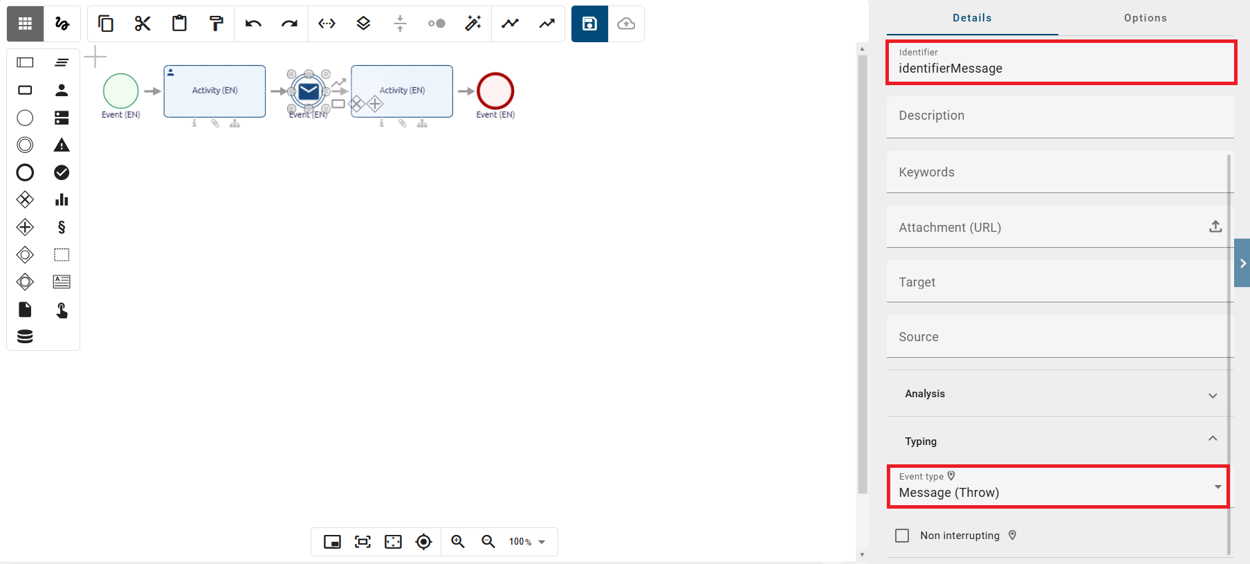
To define which information is passed to the subprocess, switch to the Options panel in the right sidebar and select the Process Execution Editor. In the Payload Configuration of the Process Execution Editor, you can define additional variables in a JSON structure that will be passed to the next process. This allows process variables to be transferred in a targeted way.
JSON structure to copy:
[
    {
        "sourceVariable": "department"
    },
    {
        "sourceVariable": "employeeId"
    }
]
In the example above, the variables department and employeeId are passed automatically. As soon as the event type Message (Throw) is triggered, the updated value is set in the Payload. The next process then immediately receives the new information for the variables department and employeeId, without requiring any additional mapping.
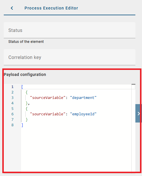
Hint
Please note that predefined system variables (e.g., _case.name) cannot be used within the JSON structure when passing variables.
To configure the receiving event that allows the start or continuation of your subprocess, open a diagram representing your subprocess. In this diagram, enter the identifier that you selected in the main process. Then select the event type Message (Catch). This ensures that the sent message is uniquely assigned, allowing the subprocess to receive the data and start or continue the process accordingly.
Note
Since the variables are transferred directly to the subprocess, they are immediately available without any additional assignment and can be used directly.
How can I process waiting events using the REST API?
With the GBTEC Work Orchestrator REST API, in addition to creating new cases from external applications, you can also process waiting events. To use this feature, you need the REST endpoint and an API key that you pass along in the Request Header.
You can use the following link to the Swagger UI to view the available public endpoints and process a waiting event. At the top right of the screen, under Select a definition, select GBTEC Work Orchestrator API. In the list that appears then, you will find the Throw a signal event endpoint, where you can edit the variables and process a waiting event.
Tip
If the link to the Swagger UI does not work, please enter the following URL manually: https://{{host}}/public/webjars/swagger-ui/index.html, where {{host}} represents your host.
Hint
The old {{host}}/process-execution/external/tenants/{{tenantId}}/stages/{{stageId}}/signal-events REST endpoint is currently still available. However, please use the new endpoint in the future.
Hint
If you have previously worked with the old REST endpoint and are now working with the Swagger UI, you will need to generate a new API key. Please note that the new API key will need to be adjusted accordingly in the REST call.
How can I access the metadata of an output document?
To access the metadata of an output document, an output document must be available in the process execution. This applies to output documents that were generated for task forms, service tasks, reports, or activities.
Once a document has been stored in the process execution, you can view the size, date, and name of the document. To check this information, open the context menu using the three dots next to the corresponding process step and select the option Edit process variables. This will take you to the variables where the document information is displayed.
The name corresponds to the stored identifier. If no identifier has been defined, a random name is assigned automatically. This ensures that it is always possible to trace which file was created or stored as part of the process.
How can I integrate an application into a task form?
Application objects that you have modeled in GBTEC Process Design can also be integrated into GBTEC Work Orchestrator. They are available to the users within the process flow. In order to be able to integrate an application object, it must have a connection to an activity object in your diagram in GBTEC Process Design.
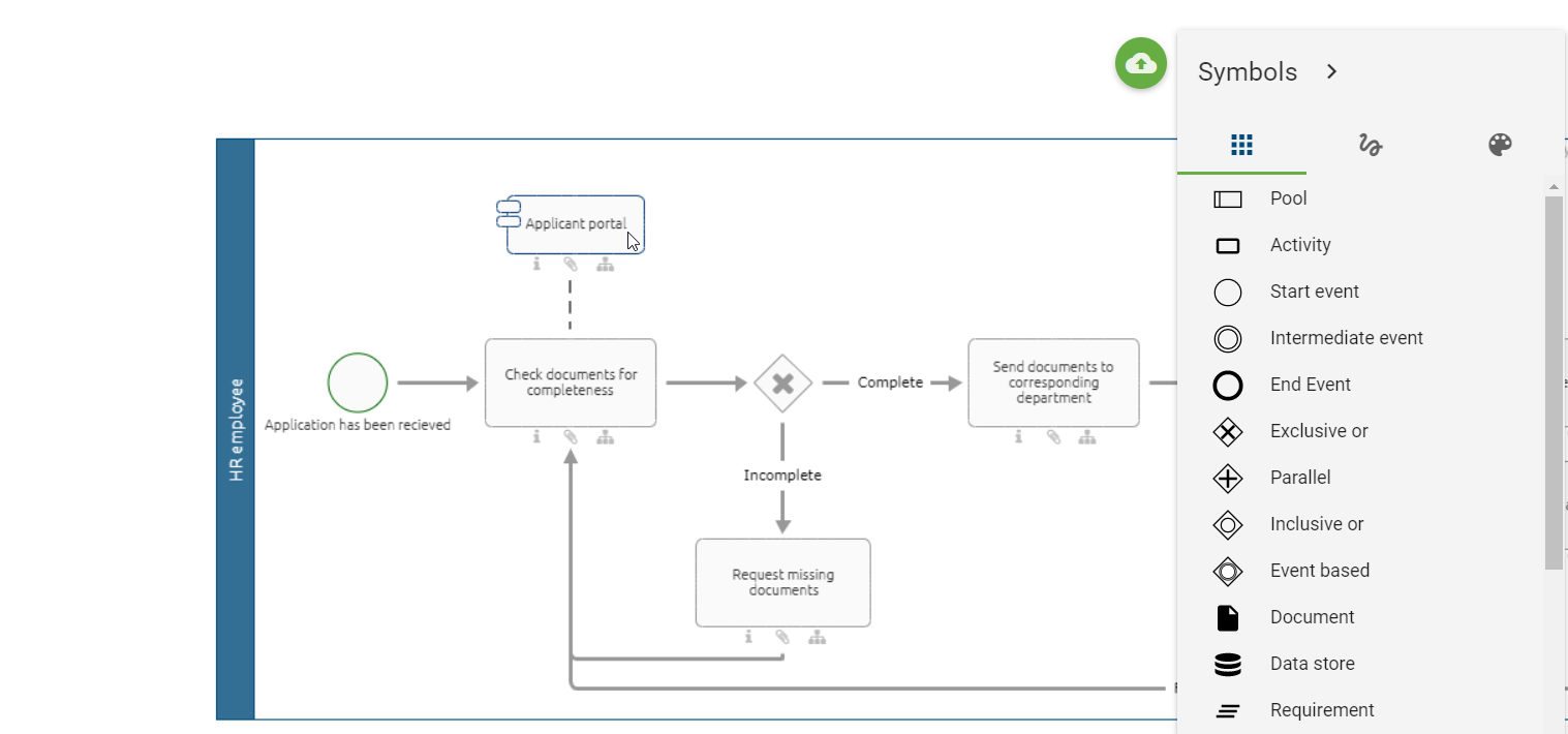
Within the Details of the application object, you can link the application of your choice to make it accessible in GBTEC Work Orchestrator. To do so, use the attribute Integration link within the section Automation. Analog to the attribute Attachment (URL), you can add links or alternatively upload documents.
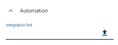
When adding a link to one of your applications, you can also integrate process variables if you know that they will be defined before the respective task is reached. To do so, add the respecting variable name between two curly braces at the appropriate place in the path. Here you can see an example of what such a path could look like:
mailto://{{emailRecipient}}?subject={{emailSubject}}&cc={{emailRecipientCC}}&body={{emailText}}
In this example, the process variables are “emailRecipient”, “emailSubject”, “emailRecipientCC” and “emailText”.
When entering a variable as a placeholder, you can choose between JUEL expression and String replacement. You specify the desired variant directly in the drop-down menu in the upper area of the Process Execution Editor in the Options panel in the right sidebar.
Please note that both variants are not supported at the same time. Diagrams that were created before the 8.0.0 version automatically use the previous string replacement logic. For newly created diagrams, however, the JUEL variant is now preselected by default. You can adjust the selected option at any time, but switching new diagrams to String replacement is not recommended.
Tip
You can find more information about JUEL expressions here.
Once you have defined your attribute and your diagram meets all requirements to be displayed in GBTEC Work Orchestrator, the application will be displayed under the section Applications within the task form. If a title is available for the link, it will be displayed below the application name. Otherwise, the URL is displayed. You can access the application via the Integration Link.
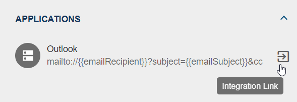
Multiple links can also be integrated into an application. When this is the case, a context menu containing all the links is displayed after the Integration Link has been selected. You can then open the desired link by clicking on it.
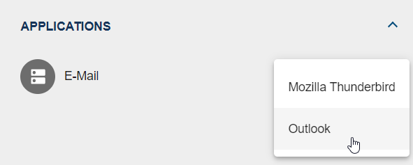
Formulas
Formulas can be used for different purposes. For example, you can use them in the form editor to calculate values. You can also use them to make your task forms more dynamic.
This chapter provides an overview of all existing formulas and how to use them correctly. At the end of this chapter, you will find some examples of what you can calculate with these formulas. Additionally, you will find an example which explains how you can make your form dynamic.
Most of the formulas you can use in Microsoft Office Excel are supported and work the same as in Excel. It is also possible to write formulas using simple JavaScript syntax. For example, 2+6 would also be a valid formula and would return 8.
Some formulas use parameters. Of course, you can also use existing process variables. If you want to use already existing process variables, you need to enclose them in two curly braces (e.g. {{VariableName}}).
If you use dates or strings as the data type for parameters, you need to enclose them in single quotation marks (e.g. LEN('example')).
Tip
Formulas can be nested within each other. That means you can use a formula as an input parameter for another formula.
Which formulas exist?
Note
This section is currently under revision and therefore not complete. A complete overview of all usable formulas can be found in the documentation of Formula.js.
The formulas can be separated into six different categories:
Date formulas
When using date formulas, you will often need parameters in the datetime format.
The data type datetime can be written in different formats. If you are not using predefined process variables, you need to make sure that you are using the correct form. A datetime without time looks like the following: 'month/day/year', e.g. '06/14/2021' for June 14, 2021. Alternatively, you can use 'day-month-year', e.g. '14-Jun-2021'. Note that it is important to abbreviate the month according to the table below. If you also want to use a timestamp, you need to use one of the formatting options above and append 'hh:mm:ss AM/PM'. The use of seconds is optional. For example, '06/14/2021 10:47:32 AM' would represent 10:47 AM on June 14 2021. More examples using datetime variables can be found here.
Month |
January |
February |
March |
April |
May |
June |
|---|---|---|---|---|---|---|
Abbr. |
Jan |
Feb |
Mar |
Apr |
May |
Jun |
Month |
July |
August |
September |
October |
November |
December |
Abbr. |
Jul |
Aug |
Sep |
Oct |
Nov |
Dec |
Extract data from dates
There are various date formulas that you can use to extract specific data from a date.
YEAR({{datetime}})returns the year of a datetime value in the range of 1900-9999.
MONTH({{datetime}})returns the month of a datetime value in the range of 1-12.
WEEKNUM({{datetime}},[{{mode}}])returns the week number of a datetime value in the range of 1-53. The parameter mode defines whether the week starts on Sunday (mode = 1) or on Monday (mode = 2). If you do not use this parameter, the default value is mode = 1.
ISOWEEKNUM({{datetime}})returns the week number of a datetime value. The first week of the year is the week which has the first Thursday in it.
WEEKDAY({{datetime}}, [{{mode}}])returns the number of the day of a datetime value in the range of 1-7. The parameter mode behaves equivalent to the one in the formulaWEEKNUM.
DAY({{datetime}})returns the day of a datetime value in the range of 1-31.
HOUR({{datetime}})returns the hour of a datetime value in the range of 0-23.
MINUTE({{datetime}})returns the minute of a datetime value in the range of 0-59.
SECOND({{datetime}})returns the second of a datetime value in the range of 0-59.
Calculate time spans
The following table shows you the different modes and which parts of the week belong to the weekend.
<mode> |
Weekend |
<mode> |
Weekend |
|---|---|---|---|
1 |
Saturday and Sunday |
11 |
only Sunday |
2 |
Sunday and Monday |
12 |
only Monday |
3 |
Monday and Tuesday |
13 |
only Tuesday |
4 |
Tuesday and Wednesday |
14 |
only Wednesday |
5 |
Wednesday and Thursday |
15 |
only Thursday |
6 |
Thursday and Friday |
16 |
only Friday |
7 |
Friday and Saturday |
17 |
only Saturday |
With the following formulas you can measure the time span between two dates.
DAYS({{enddate}}, {{startdate}})returns the difference in days between a start date and an end date. You can find a concrete example here.
WORKDAY({{date}}, {{k}})returns the k-th next workday starting at date. Workdays are all days of the week except Saturday and Sunday.
WORKDAYINTL({{date}}, {{k}}, {{mode}})returns the k-th next workday from date. mode defines which part of the week belongs to the weekend. Above you can find a table with an overview of all available weekend definitions.
NETWORKDAYS({{startdate}}, {{enddate}}, [{{listOfHolidays}}])returns the number of work days (Monday-Friday) between two dates. Optionally, you have the possibility of adding holidays. They will also be excluded from counting. A more specific example can be found here.
NETWORKDAYSINTL({{startdate}}, {{enddate}}, {{mode}}, [{{listOfHolidays}}]returns the number of workdays between two dates. mode defines which part of the week belongs to the weekend. Above you can find a table with an overview of all available weekend definitions.
DAYS360({{start}}, {{end}}, {{method}})returns the difference in days between a start and an end date. This formula assumes that a year has 360 days, therefore every month has 30 days. You can use the method parameter to specify whether you want to calculate the difference using the US method (method = FALSE()) or the European method (method = TRUE()). For example,DAYS360('12/1/2021','1/1/2022',TRUE())would return 30 days. The difference between these two methods is explained below:
European method: If the start or end date falls on the 31st of a month, the formula will calculate with the 30th day of the month instead.
US-american method: If the start date falls on the 31st of a month, the formula will calculate with the 30th instead. If the end date falls on the 31st of a month, what the formula calculates depends on the start date. If the start date is earlier than the 30th of a month, the end date is set to the 1st day of the following month. Otherwise, the end date is set to the 30th.
YEARFRAC({{start}}, {{end}}, {{mode}})returns the time span between two dates as a number. With the parameter mode you got five different options to calculate the difference.
mode = 0: The difference will be calculated with the 30-day month US-American definition (see formula
DAYS360) and divided by 360.mode = 1: The actual difference in days will be divided by the actual number of days in the year.
mode = 2: The actual difference in days will be divided by 360.
mode = 3: The actual difference in days will be divided by 365.
mode = 4: The difference will be calculated with the 30-day month european definition (see formula
DAYS360) and divided by 360.
DATEDIF({{startdate}}, {{enddate}}, {{unit}})returns the difference between two dates in a specified unit. You can choose between the following units:
Y: Difference of fully completed years.
M: Difference of fully completed months.
D: Difference of days.
MD: Difference of days; months and years are being ignored.
YM: Difference of months; days and years are being ignored.
YD: Difference of days; years are being ignored.
Current date
You can use the following formulas to get the current date.
TODAY()returns the current date in the datetime format.
NOW()returns the current date, including the current time in the datetime format.
Convert into datetime format
With the following formulas you can convert dates or other data types into the datetime format.
DATE({{year}}, {{month}}, {{day}})lets you create a variable in the datetime format.
TIME({{hour}}, {{minute}}, {{second}})returns a time span as floating point number in days. Therefore 24 hours correspond to the value 1, 12 hours to the value 0.5, etc.
DATEVALUE({{string}})converts a string, if possible, into a valid datetime format.
TIMEVALUE({{string}})converts a string, if possible, into a time span as floating point number (seeTIME).
Adding timespans
EDATE({{start}}, {{k}})will add k months to start and return the result. k can be negative to calculate dates in the past. For example,EDATE('2/5/2021',3)will return the 5th May 2021.
EOMONTH({{start}}, {{k}})will add k months to start and return the end of the corresponding month. k can be negative or zero. For example,EOMONTH('2/1/2021',3)will return the 31st May 2021.
Note
If you receive an error message when entering a formula, the problem may be related to the date function. In this case the error can be resolved by using .toISOString(), as in the following example WORKDAY({{createdDate}}, 10).toISOString().
Formatting date variables with DateUtils.format
As a ProcessApp Creator, you can use the helper function DateUtils.format(date, pattern,timeZone) to convert date variables into a uniform, easy-to-read format. This function supports both standard date formats and ISO formats and allows time zones to be taken into account. It is based internally on the Java Development Kit Version 17 API specifications. Information on the formatting patterns used (SimpleDateFormat) can be found at the following link, and information about time zones (TimeZone API) at this link
You can use this helper function to format date variables in service tasks with REST calls, script tasks using AI, send tasks, intermediate timer events, and when linking applications. Examples of how to use the helper function are listed below:
Example: format date variable in string
DateUtils.format(startDate, "dd.MM.yyyy") formats the variable “startDate” with the value Wed Jul 09 00:00:00 UTC 2025 to 09.07.2025.
Example: format date variable with ISO pattern
DateUtils.format(eventDate, "yyyy-MM-dd") formats the variable “eventDate” with the value 2024-12-31T23:59:59Z to 2024-12-31.
Example: format date variable with a time zone
DateUtils.format(eventDate, "yyyy-MM-dd HH:mm:ss XXX", "GMT-8:00") formats the variable “eventDate” with the value 2025-01-01T00:00:00Z taking into account the time zone GMT-8 to 2024-12-31 16:00:00 -08:00.
Example: format date variable with an invalid time zone
DateUtils.format(eventDate, "yyyy-MM-dd HH:mm:ss XXX", "not-valid") formats the variable “eventDate” with the value 2025-01-01T00:00:00Z if the time zone is invalid and returns 2025-01-01 00:00:00 Z.
Example: format date variable with a “null” value
DateUtils.format(dueDate, "yyyy-MM-dd") formats the variable “dueDate” with the value null and returns an empty string.
Example: format date variable with an invalid or unsupported pattern
DateUtils.format(createdAt, "invalid-pattern") formats the variable “createdAt” with the value 2025-01-01T00:00:00Z with an invalid pattern and returns the date in ISO format.
Note
Date formatting with DateUtils.format() is only possible if the placeholder evaluation engine is set to “JUEL expression” in the Process Execution Editor. DMN tables are currently not supported.
Logic formulas
Logic formulas can be used for evaluating logical expressions.
Note
Logical expressions are always TRUE or FALSE.
TRUE()returns the logic value TRUE.FALSE()returns the logic value FALSE.
Logical operators
AND({{log_a}}, {{log_b}}, ...)returns TRUE if all expressions are TRUE. Returns FALSE otherwise.
OR({{log_a}}, {{log_b}}, ...)returns TRUE if at least one expression is TRUE. Returns FALSE otherwise.
XOR({{log_a}}, {{log_b}}, ...)returns TRUE if exactly one expression is TRUE. Returns FALSE otherwise.
NOT({{log_a}})negates the parameter. TRUE becomes FALSE, FALSE becomes TRUE.
Conditional expressions
IF({{cond}}, {{value1}}, {{value2}})returns depending on the condition a different value. If cond evaluates to TRUE, value1 will be returned, otherwise value2 will be returned.
IFS({{cond1}}, {{value1}}, {{cond2}}, {{value2}}, ...)allows the possibility of multiple evaluations. It will be checked if one of the conditions evaluates to TRUE, the corresponding value will be returned. If a condition is FALSE the next condition will be checked until a condition which is TRUE is found. But only the first condition that evaluates to TRUE will return a value. For example,IFS(TRUE(), 2, TRUE(), 5)returns 2.
SWITCH({{value}}, {{check_1}}, {{return_1}}, {{check_2}}, {{return_2}})compares the parameter value with check_1, check_2, etc. until a match is found. The formula returns the corresponding return value then. For example,SWITCH(7,9,'nine',7,'seven')would return seven.
IFERROR({{formula}}, {{expression}})evaluates the inner formula formula and returns its return value. If the formula returns an error, expression is returned. For example,IFERROR(8/2,'Error')would return 4, butIFERROR(8/0,'Error')would return Error. Of course, you can nest any other formula inside this formula.
String formulas
If your formula requires a parameter of the type string, then you need to enclose it in single quotation marks, for example, LEN('Example'). Alternatively, you can use predefined process variables. You can find an explanation for that here.
String extraction
With the following formulas you can extract strings or specific information out of a string.
RIGHT({{string}}, {{num}})returns the num right characters of string. For example,RIGHT('Profit margin',6)would return margin.
LEFT({{string}}, {{num}})returns the num left characters of string.
MID({{string}}, {{startPos}}, {{num}})returns a part of string. Starting at startPos, num characters will be returned. For example,MID('Pete drives his car', 6, 6)returns drives.
LEN({{string}})returns the number of characters in string.
REPT({{string}}, {{num}})repeats string num-times. For example,REPT('x',5)returns xxxxx.
SEARCH({{searchTerm}}, {{string}})searches in string for searchTerm and returns the character index at which the searched string starts. For example,SEARCH('margin', 'Profit Margin')would return 8. If the string cannot be found, the formula returns an error.
FIND({{searchTerm}}, {{string}}, [{{startPos}}])searches in a string string for a search term searchTerm and returns the first occurrence of it. startPos allows you to start the search at a different character. For example,FIND('i','Pete drives his car',10)would return 14. If you do not use the parameter startPos, the formula starts searching at the first character.
REGEXEXTRACT({{string}}, {{expression}})searches in string for the regular expression expression and returns the index of the first occurrence.
String manipulation
With the following formulas, you can manipulate a string.
LOWER({{string}})converts string into lowercase letters.
UPPER({{string}})converts string into uppercase letters.
PROPER({{string}})converts the first character of string into an uppercase letter and the following characters into lowercase letters. For example,PROPER('bicYCle')returns Bicycle.
TRIM({{string}})deletes multiple spaces in string.
CLEAN({{string}})returns string without non-printable characters.
CONCATENATE({{string1}}, {{string2}}, ...)concatenates two or more strings into one string. For example,CONCATENATE('John', ' ', 'Doe')returns John Doe.
REPLACE({{string}}, {{pos}}, {{num}}, {{replace}})replaces a character in a string with another character. Starting with the character at the position pos, num characters are replaced by the string replace. For example,REPLACE('abcdefghijk', 6, 5, '*')will returnabcde*k.
SUBSTITUTE({{string}}, {{old}}, {{new}}, [{{pos}}])substitutes in string the character old by new. If you do not want to replace all occurrences of old, you need to add the parameter pos. This will define which character gets replaced. For example,SUBSTITUTE('Q1-2011', '1', '2')would replace all 1’s by 2’s, therefore returning Q2-2022, butSUBSTITUTE('Q1-2011', '1', '2', 1)would replace only the first occurrence of 1 therefore returning Q2-2011.
SPLIT({{string}}, {{delimiter}})will split string at every position where delimiter is and returns the results as a list. For example,SPLIT('Peter&Max&Antonia', '&')will return [‘Peter’, ‘Max’, ‘Antonia’].
String comparison
With the following formula, you are able to check whether two strings are the same or not.
EXACT({{string1}},{{string2}})checks if two strings are the same. This function is case-sensitive. It will return TRUE if the strings are the same, otherwise it will return FALSE.
REGEXMATCH({{string}}, {{expression}})checks whether the regular expression expression is in string or not. It will return TRUE if the regular expression matches at least once and will return FALSE otherwise.
T({{var}})checks if var is a string. If var is a string, it will be returned, otherwise an empty string will be returned.
Convert strings
With the following formulas, you can convert numbers into strings and vice versa. These formulas use the unicode standard.
UNICHAR({{number}})formats a value and converts it into a string.
UNICODE({{character}})formats a string and converts it to a number.
ARABIC({{string}})converts a roman number string into the Arabic number system. For example,ARABIC('XVI')would return 16.
ROMAN({{number}})converts an Arabic decimal number number into the roman number system. For example,ROMAN(16)would return XVI.
Math formulas
Round numbers
With the following formulas you can round numeric values.
ROUND({{number}}, {{n}})rounds number to n decimal places.
ROUNDDOWN({{number}}, {{n}})rounds number down to n decimal places.
ROUNDUP({{number}}, {{n}})rounds number up to n decimal places.
INT({{number}})rounds number down to the next integer.
FLOOR({{number}}, {{i}})rounds number down to the nearest multiple of i (for example,FLOOR(3.1415,2)will return 2).
FLOORMATH({{number}}, {{i}}, {{mode}})rounds number down to the nearest multiple of i. mode decides whether you want to round away or towards zero. mode = 0 rounds away from zero (FLOORMATH(-12.1,1,0)returns -13). mode = 1 rounds towards zero (FLOORMATH(-12.1,1,1)returns -12).
CEILING({{number}}, {{i}})rounds number up to the nearest multiple of i (for example,CEILING(3.1415,3)returns 6).
CEILINGMATH({{number}}, {{i}}, {{mode}})rounds number up to the nearest multiple of i. mode decides whether you want to round away or towards zero. mode = 1 rounds away from zero (CEILINGMATH(-4.1,1,1)returns -5). mode = 0 rounds towards zero (CEILINGMATH(-4.1,1,0)returns -4).
TRUNC({{number}}, {{n}})truncates number to n decimal places (e.g.,TRUNC(2.895,1)returns 2.8).
ODD({{number}})rounds number up to the nearest odd number.
EVEN({{number}})rounds number up to the nearest even number.
SIGN({{number}})determines the sign of a number. Returns 1 if the number is positive, returns -1 if the number is negative and returns 0 if the number is 0.
Arithmetic operations
QUOTIENT({{dividend}},{{divisor}})performs division and returns only the integer portion of the division result. Use this function when you want to discard the remainder of the division.
MOD({{dividend}}, {{divisor}})returns the remainder after a number is divided by a divisor.
POWER({{number}},{{power}})returns the result of number to the power of power.
FACT({{number}})returns the factorial of number.
ABS({{number}})returns the absolute value of number.
SQRT({{number}})returns the square root of number.
SQRTPI({{number}})returns the square root of{{number}} * Pi.
MAX({{num1}},{{num2}}, ...)returns the largest number value of the parameters. Logical values and text are being ignored.
MAXA({{num1}}, {{num2}}, ...)returns the largest number value of the parameters. Logical values and text are not being ignored.
MIN({{num1}},{{num2}}, ...)returns the smallest number value of the parameters. Logical values and text are being ignored.
MINA({{num1}}, {{num2}}, ...)returns the smallest number value of the parameters. Logical values and text are not being ignored.
SUM({{num1}},{{num2}}, ...)returns the sum of all parameters.
SUMIF({{range}}, {{criterion}}, {{[sum_range]}})returns the sum of numbers in a list that meet a specific criterion. The criterion is applied to the list range. If that is not the list that should be summed up, the parameter sum_range must be used.
SUMPRODUCT({{list1}}, {{list2}})returns the sum of the products of the lists.
SUMSQ({{num1}}, {{num2}}, ...)returns the sum of the squares of the numbers.
SUMX2PY2({{list1}}, {{list2}})returns the sum of the sum of squares of the corresponding values in two lists.
SUMXMY2({{list1}}, {{list2}})returns the sum of squares of differences of corresponding values in two arrays.
PRODUCT({{num1}},{{num2}}, ...)returns the product of all parameters.
LCM({{num1}}, {{num2}}, ...)returns the least common multiple of all parameters.
GCD({{num1}}, {{num2}}, ...)returns the greatest common divisor of all parameters.
Information functions
ISEVEN({{number}})returns TRUE when number is even. Otherwise it will return false.
ISODD({{number}})returns TRUE when number is odd. Otherwise it will return false.
Trigonometric functions
RADIANS({{number}})converts degrees into radians. For example,RADIANS(180)returns 3.14159.
SIN({{number}})returns the sine of number.
SINH({{number}})returns the hyperbolic sine of number.
COS({{number}})returns the cosine of number.
COSH({{number}})returns the hyperbolic cosine of number.
COT({{number}})returns the cotangent of number.
COTH({{number}})returns the hyperbolic cotangent of number.
CSC({{number}})returns the cosecant of number.
CSCH({{number}})returns the hyperbolic cosecant of number.
SEC({{number}})returns the secant of number.
SECH({{number}})returns the hyperbolic secant of number.
TAN({{number}})returns the tangent of number.
TANH({{number}})returns the hyperbolic tangent of number.
ASIN({{number}})returns the inverse sine of number.
ASINH({{number}})returns the inverse hyperbolic sine of number.
ACOS({{number}})returns the inverse cosine of number.
ACOSH({{number}})returns the inverse hyperbolic cosine of number.
ACOT({{number}})returns the inverse cotangent of number.
ACOTH({{number}})returns the inverse hyperbolic cotangent of number.
ATAN({{number}})returns the inverse tangent of number.
ATANH({{number}})returns the inverse hyperbolic tangent of number.
Logarithm functions
LN({{number}})returns the natural logarithm of number.
LOG({{number}}, {{base}})returns the logarithm of number to the base. If the parameter base is not given, the standard value will be 10.
LOG10({{number}})returns the logarithm of number to the base 10.
Random numbers
RAND()returns a random decimal number between 0 and 1.
RANDBETWEEN({{num1}},{{num2}})returns a random integer between num1 and num2.
Finance formulas
Variable |
Meaning |
|---|---|
|
describes the number of periods |
|
describes the number of periods per year |
|
describes the present / current value of an investment |
|
describes the future value of an investment |
|
describes whether a payment is due at the end of the payment (type = 0) or at the |
|
describes the period you want to inspect. The value can only be between 1 and |
|
describes the payment made each period |
Other variables will be explained with the formula.
ACCRINT({{issue}}, {{first_interest}}, {{settlement}}, {{rate}}, {{par}}, {{frequency}}, {{[basis]}}, {{[calc_method]}})returns the accrued interest for a security that pays periodic interest. Issue is the security’s issue date. Settlement is the date after the issue date when the security is traded to the buyer. Frequency describes the number of payments in a year.
CUMPINT({{rate}}, {{nper}}, {{pv}}, {{start_period}}, {{end_period}}, {{type}})returns the cumulative interest paid on a loan between start_period and end_period.
CUMPRINC({{rate}}, {{nper}}, {{pv}}, {{start_period}}, {{end_period}}, {{type}})returns the cumulative principal paid on a loan between two dates.
DB({{cost}}, {{salvage}}, {{life}}, {{period}}, {{[month]}})returns the depreciation of an asset using the fixed-declining balance method. cost describes the initial cost of the asset. Period describes the period for which you want to calculate the depreciation. It must have the same unit as the variable life.
DDB({{cost}}, {{salvage}}, {{life}}, {{period}}, {{[factor]}})returns the depreciation using the double-declining balance method. The needed variables are the same as in the formulaDB.
DOLLARDE({{fractional_Dollar}}, {{fraction}})converts a number expressed as an integer part and a fraction part into a decimal number, for example,DOLLARDE(1.02,16)returns the value 1.125 (1 + 2/16).
DOLLARFR({{decimal_Dollar}}, {{fraction}})converts a decimal number into a number that has an integer and a fraction part, for example,DOLLARFR(1.125,16)returns 1.02.
EFFECT({{nominal_rate}}, {{npery}})returns the effective annual interest rate.
FV({{rate}}, {{nper}}, {{pmt}}, {{[pv]}}, {{[type]}})returns the future value of an investment.
FVSCHEDULE({{Principal}}, {{Schedule}})returns the future value of an investment where interest rates are not constant. The variable Schedule must be given in list form.
IPMT({{rate}}, {{per}}, {{nper}}, {{pv}}, {{[fv]}}, {{[type]}})returns the interest payment for a given period.
IRR([{{value1}}, {{value2}}, ...], {{guess}})returns the internal rate of return of an investment. guess is used to determine at which return rate the algorithm starts to calculate. The closer guess is to the real rate, the preciser is the value calculated by the formula. Normally, 0.1 (10%) is a good estimation for the IRR.
ISPMT({{rate}}, {{per}}, {{nper}}, {{pv}})returns the interest over a specific time, with even interest rates and principal payments.
MIRR({{values}}, {{finance_rate}}, {{reinvest_rate}})returns the modified internal rate of return for a series of periodic cash flows. values must be given in list form. finance_rate is the interest rate you pay on the money, reinvest_rate is the interest rate you receive from reinvesting the cash flows.
NOMINAL({{effect_rate}}, {{npery}})returns the nominal annual interest rate.
NPER({{rate}}, {{pmt}}, {{pv}}, {{[fv]}}, {{[type]}})returns the number of periods for an investment.
NPV({{rate}}, {{value1}}, {{value2}}, ...)returns the net present value of an investment by using the discount rate rate. value1, value2 … represent the corresponding cash flows.
PDURATION({{rate}}, {{presentValue}}, {{futureValue}})returns the number of periods needed by an investment presentValue to reach futureValue. rate is the interest rate per period.
PMT({{rate}}, {{payments}}, {{presentValue}})calculates the payment for a loan based on constant payments and a constant interest rate rate. payments denotes the number of payments. presentValue is the amount of the loan.
PPMT({{rate}}, {{per}}, {{nper}}, {{pv}}, {{[fv]}}, {{[type]}})returns the payment on the principal for a given period.
PV({{rate}}, {{nper}}, {{pmt}}, {{[fv]}}, {{[type]}})returns the present value of an investment.
RATE({{nper}}, {{pmt}}, {{pv}}, {{[fv]}}, {{[type]}}, {{[guess]}})returns the interest rate per period of an annuity.
Conversion into different numeral systems
The formulas for converting numbers into different numeral systems are similar to each other: XXX2YYY({{number}}). Here XXX stands for the original numeral system and YYY for the target numeral system. In the table below you can find the abbreviations and the usable numbers and characters of the different numeral systems. For example, BIN2DEC({{number}}) will convert number from the binary system to the decimal system.
Numeral system |
Abbreviation |
Usable characters |
|---|---|---|
Binary |
BIN |
0-1 |
Decimal |
DEC |
0-9 |
Hexadecimal |
HEX |
0-F |
Octal |
OCT |
0-7 |
Additionally, there are two more general formulas which you can use to convert numbers into different numeral systems.
BASE({{number}}, {{base}})converts a decimal number into a number of a numeral system with the base.
DECIMAL({{string}}, {{base}})converts a number of a different numeral system with the base base into the decimal system.
Therefore, the formula DECIMAL('101',2) and the formula BIN2DEC(101) have the same output.
Statistic formulas
Basics
AVERAGE({{num1}}, {{num2}}, ...)returns the arithmetic mean of all numeric parameters.
AVERAGEA({{num1}}, {{num2}}, ...)returns the average of all variables. Logical values and texts are not ignored.
AVERAGEIF({{range}}, {{criteria}}, {{[average_range]}})returns the average of the parameters that meet the given criterion. The parameter with the exception of the criterion must be given in form of a list.
AVERAGEIFS({{average_range}}, {{criteria_range1}}, {{criteria1}}, {{criteria_range2}}, {{criteria2}}, ...)returns the average of the parameters that meet the given criteria. The parameter, with the exception of the criteria, must be given in form of lists.
MEDIAN({{num1}}, {{num2}}, ...)returns the median of all numeric parameters.
COUNT({{num1}}, {{num2}}, ...)returns the number of values.
COUNTIF({{range}}, {{criteria}})returns the number of elements in a list, that meet a given criterion.
COUNTIFS({{criteria_range1}}, {{criteria1}}, {{criteria_range2}}, {{criteria2}}, ...)returns the number of elements in a list that meet the given criteria.
LARGE([{{num1}}, {{num2}}, ...],{{k}})returns the k-th largest number. For example:LARGE([2,3,5],2)returns the second largest number 3.
SMALL([{{num1}}, {{num2}}, ...],{{k}})returns the k-th smallest number.
Examples for formulas
How do I calculate a leap year?
If you want to calculate whether a year is a leap year, you cannot use a predefined formula. But you can easily create your own formula to do this. First, you need a number input field in your form. In this case, the variable is called year. In GBTEC Work Orchestrator, you can enter the year you would like to check in the number field.
Now use the following formula:

As you can see, the formula consists of multiple nested formulas. First, you create a valid variable in the datetime format with DATE({{year}},02,29). Depending on the year, the date will be March 1 (if the year is not a leap year) or February 29 (if the year is a leap year).
Using the formula MONTH will return the month of the given date as an integer. As already explained, the return value will be 2 (if the year is a leap year and therefore the month is February) or 3 (if the month is March).
Last but not least, we use the formula EXACT to check whether our result is 2 or not. If it is true and the year is a leap year, it returns TRUE, otherwise it returns FALSE.
In GBTEC Work Orchestrator it will look like this:
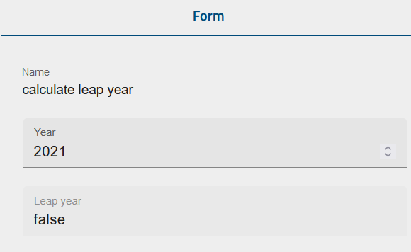
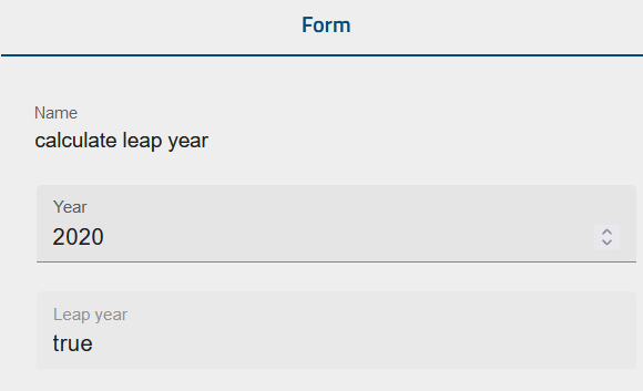
How do I calculate workdays?
In the following, we provide an example of how to use different formulas (for example, how to calculate the number of workdays between two dates).
In this example, you want to carry out a project and want to calculate how many working hours the company can offer in a given period of time.
This example is deliberately kept simple and does not reflect all relevant activities and aspects. It is intended to give you an overview of what you can accomplish with formulas.
First, you could use form fields to enter some key aspects of our project. Alternatively, you could get the data from other processes as well. In this example, we only consider the start and end dates of the project, the number of participating employees, and their average hours they worked on the project.
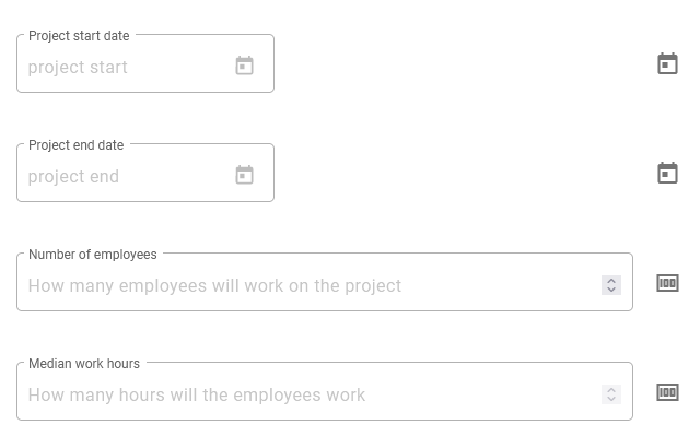
The start date and end date fields are date fields. The fields for entering the number of employees and their average hours worked are number fields. The IDs of the corresponding form fields in this example are:
start date: start
end date: end
number of employees: people
number of working hours: hours
With these values, it is now possible to calculate the following variables.
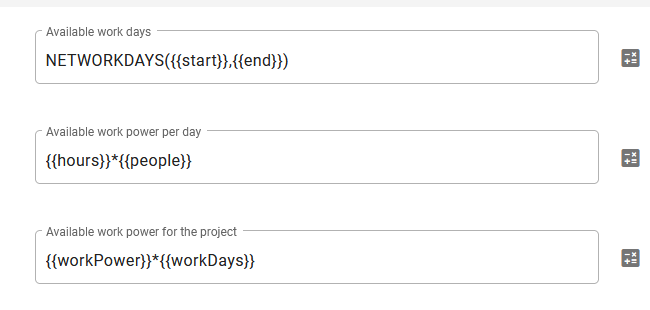
The first formula calculates the number of workdays (the variable ID is workDays) between the start and the end dates. Here you can find the details of the formula NETWORKDAYS.
The second calculation is the available work power per day (variable: workPower). To do this, we simply multiply the number of employees by their average working hours per day.
Finally, the total project capacity is calculated by multiplying the number of workdays by the available work power per day.
When you now open your process in GBTEC Work Orchestrator, it will look like the following. The three calculated values are automatically updated as soon as you enter new values.
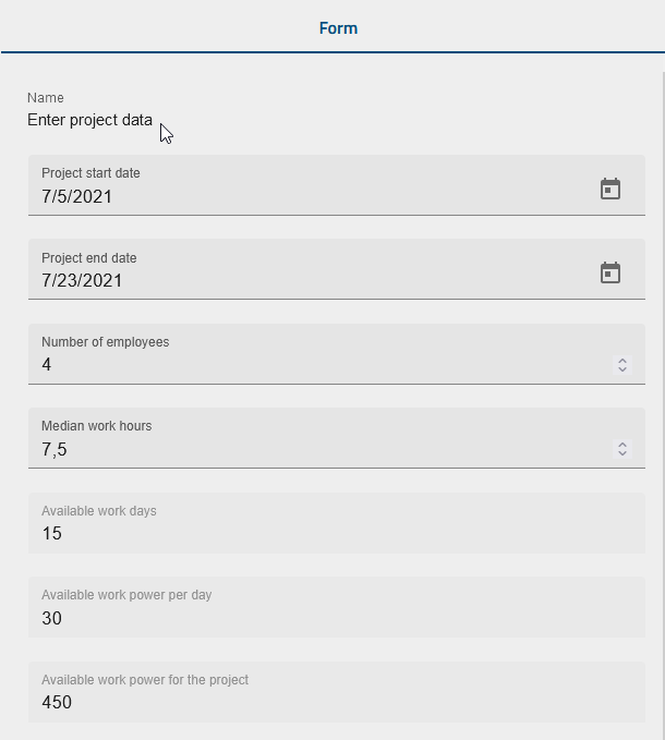
Note
If you receive an error message when entering a formula, the problem may be related to the date function. In this case the error can be resolved by using .toISOString(), as in the following example WORKDAY({{createdDate}}, 10).toISOString().
Create dynamic forms
You can also use formulas to create dynamic forms, which means that the attributes of form fields can be manipulated by user input. The following example uses a process to sell auto insurance. Our form in the form editor looks like this:
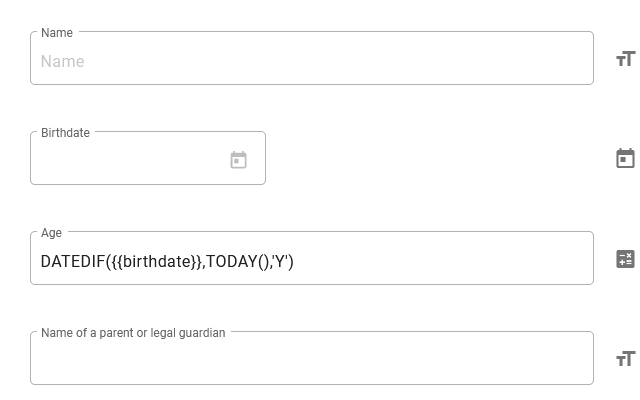
Note
If you receive an error message when entering a formula, the problem may be related to the date function. In this case the error can be resolved by using .toISOString(), as in the following example WORKDAY({{createdDate}}, 10).toISOString().
The name of a legal guardian or parent is only required if the person to be insured is younger than 21. For this, we use the attribute Hidden and choose the option Conditionally. Here we can enter a condition or formula under which circumstances the field should be hidden. In this example, it will be the case if the variable age is greater than or equal to 21. If the person is younger than 21, the field will be mandatory.
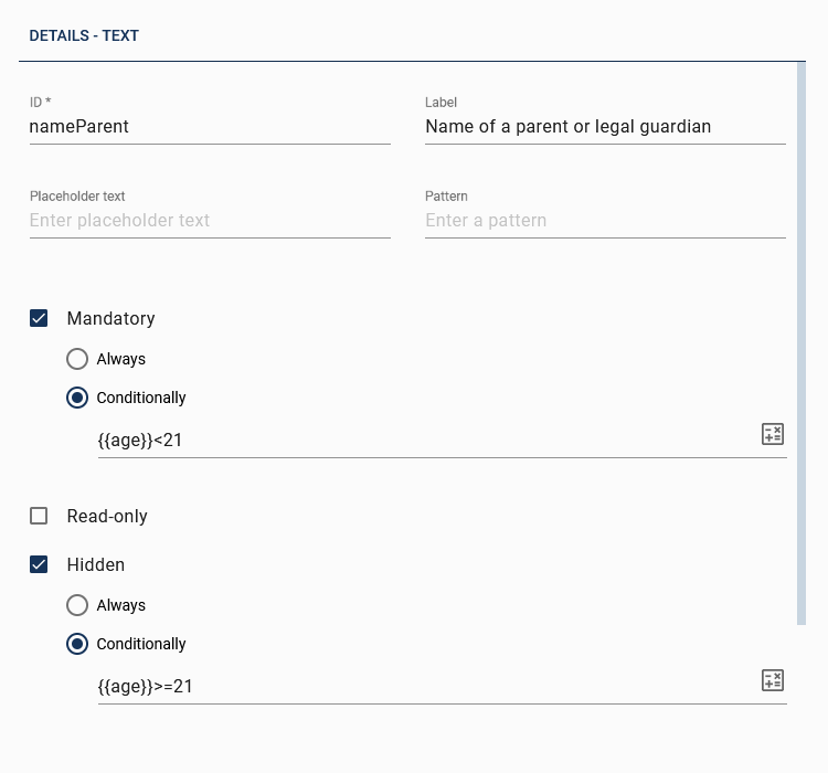
Another way to make your form dynamic is to use the attribute read-only. Below you can see a form field of the type boolean that is used to indicate whether the insurance includes fully comprehensive or not. As you can see, the field is read-only (and therefore not changeable) if the person is younger than 25, which means you can only select fully comprehensive cover if the person to be insured is older than 25.
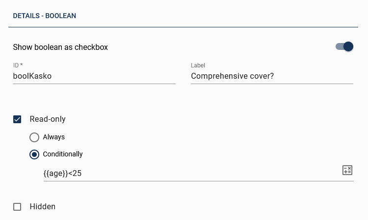
In GBTEC Work Orchestrator it is possible to start this case and see the form. In the following you can see that the field comprehensive cover cannot be changed because the person is younger than 25. However, due to the fact that the person is older than 21, you cannot enter the name of a parent or legal guardian.